From the series Introduction to Analysis for Designers...
In the previous section, we examined the boundary conditions of strength analysis. In this one, we will introduce the boundary conditions of eigenvalue analysis, as well as deepening our knowledge of strength analysis.
Eigenvalue analysis, or modal analysis, is a kind of vibration analysis aimed at obtaining the natural frequencies of a structure; other important type of vibration analysis is frequency response analysis, for obtaining the response of a structure to a vibration of a specific amplitude. Eigenvalue analysis is mainly used as a means of solving resonance problems that could cause mechanical damage to the structure. The following text focuses on explaining the method of solving these resonance problems by examining the characteristics of the boundary conditions and the mesh partitioning; the eigenvalue analysis of a plate will used as an example.
In order to solve the resonance problem, it is necessary to first examine the vibration characteristics of the designed structure. What vibration mode (deformation state) occurs due to resonance with a specific natural frequency is determined by the shape and material characteristics of the structure.
A practical method of examining the vibration characteristics of a body under free boundary conditions can be the measuring of how the vibration caused by a hammer hitting a structure passes through such structure; a vibration sensor is attached to the structure for this purpose. In the case of excitation in a short time, since an input of constant amplitude is applied in the entire frequency band, the natural frequency can be found by measuring the response to this input with the sensor. The free boundary condition, which can be achieved by placing the structure on a soft mat or hanging it in the air, is aimed to testing the designed structure in a non-constrained state.
In order to reproduce a corresponding eigenvalue analysis, the same conditions used for the practical experiment are set as boundary conditions, so that there is no need to set any other constraints. However, since the natural frequency is influenced by the mass of the design structure, it is necessary to input the mass as part of the material’s definition. This is a main difference from strength analysis, so special attention must be placed here. Figure 1 shows the results of eigenvalue analysis under free boundary conditions of a rectangular parallelepiped. Various modes of vibration, such as first bending, first twist, second twist, and second bending are generated, excluding rigid body modes, in which there is no noticeable deformation.
As mentioned in a previous chapter dedicated to mesh segmentation, eigenvalue analysis can compute a sufficiently accurate natural frequency as long as the mesh is dense enough to represent the total stiffness or mass of the structure. Natural frequencies such as the first bending and the first torsion modes, which appear at relatively low frequencies, can be obtained with high accuracy. In this regard, this type of analysis does not require much attention to mesh segmentation, unlike strength analysis, in which it is important for the accurate finding of local stresses. However, if you aim to calculate high natural frequencies to a considerable extent, you need to consider the size of the model and of the mesh elements, since they will affect stiffness calculations. When dealing with resonance problems, it is important to consider not only the value of the natural frequency but also the vibration mode. The problem itself is normally solved by examining the vibration mode at frequency of interest and reinforcing it to prevent deformation.

Figure 1: Results of Eigenvalue Analysis on a Free Plate: 1. First-order Bending; 2. First-order Twist; 3. Second-order Twist; 4. Second-order Bending,
Since the number of natural frequencies of a structure is infinite, it is important to design a frequency structure with a frequency band of a magnitude low enough to avoid resonance in the designed structure. For example, consider the noise generated by a car engine. The vibration generated by the engine is proportional to the number of revolutions in the engine due to fuel explosion, or to the upward and downward movement of the piston in the cylinder. Therefore, if the frequencies of the cylinder block, cylinder head, cam cover, and other components are equal or close to the frequencies of the engine, noise is generated due to resonance. Engine parts should be designed so that the amplitude of their vibration is small, even if they do not resonate when by themselves. The most common method to accomplish this is to first measure the noise, determine the problematic frequency and the vibration mode for such frequency by modal analysis, and then examine the means to solve this vibration mode by eigenvalue analysis.
Once you have identified the problematic vibration mode, it’s time to take a look at the relationship between natural frequency and stiffness and mass. Basically, the natural frequency is proportional to the square root of the stiffness of the designed structure divided by its mass. Therefore, the larger the stiffness and the smaller the mass, the larger the natural frequency will be.
So how do you adjust the frequency of the problematic vibration mode to be larger or smaller? The two main ways involve either changing the stiffness or changing the mass of the structure, or both. Changing the mass of a structure requires changing the size or changing the density of the material, which may very well cause problems with layout space and cost. Therefore, in general, the stiffness, and especially the rigidity, of the structure is changed to control the natural frequencies. Lowering the stiffness of a structure will cause its natural frequency to decrease, but it is quite difficult to lower the stiffness without affecting the strength of the structure.

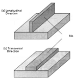
Figure 2: Addition of Ribs.
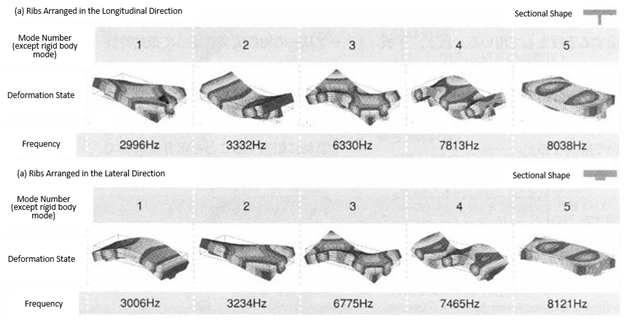
More specifically, let’s consider the method of increasing the stiffness of a plate; the results of the eigenvalue analysis are illustrated in Fig. 1. An effective approach would be to observe the deformation state at each vibration mode and to add auxiliary members to the structure in a direction in which deformation is hard to occur. For example, in the case of adding to the plate ribs of the same mass and rectangular cross-section, if the longitudinal direction of the rib is arranged perpendicular to the plate (longitudinal rib) and horizontally (transversal rib), as shown in Fig. 2, the natural frequencies and vibration modes of the modified plates will be as shown in Fig. 3 (a) and (b), respectively.

Figure 3: Results of Eigenvalue Analysis When Ribs Are Added. The frequency at which each mode appears varies depending on the placement direction of the rib: (a) When in longitudinal direction, the frequency of the bending modes is mainly increased; (b) When in transversal direction, the frequency of the twist modes is mainly increased.
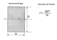
It can be seen in this example that, although ribs of the same mass are used, the frequencies at which the vibration modes occur vary depending on the direction in which they were placed. In both rib arrangements, the frequencies in the same modes were increased, but these frequencies were different for longitudinal ribs and transversal ribs. In the case of longitudinal ribs, the vibration mode of the first-order twist appears at the lowest frequency and the second mode is the first-order bending mode. On the other hand, in the case of transversal ribs, the first-order bending mode is the first mode and the first-order twist the second. The reason for this difference can be understood when considering the moment of inertia of the structure, as shown in Fig. 4; the length in the vertical direction for the transversal ribs is short. This can be appreciated by intuition, but the eigenvalue analysis confirms it.

Figure 4: Moment of Inertia for a Cross-Section. The length of the longitudinal direction (D) has a greater impact on the stiffness of the neutral axis than the length of the transversal direction (b).
Let’s take a look at the analysis results of Fig. 1 and Fig. 3 once more. On the non-ribbed plate, the first-order bending mode occurs at 2544 Hz, the first-order twist at 2958 Hz, the second-order twist at 6277 Hz, and the second-order bending at 6634 Hz. When adding longitudinal ribs, the frequency of the first-order bending becomes 3332 Hz, and of the second-order bending 7813 Hz; first-order twist is 2996 Hz, and the second-order twist is actually lowered to 6330 Hz. On the other hand, when adding transversal ribs, the frequencies of the first-order and second-order twist modes are greatly increased. That is, longitudinal ribs are effective for bending vibration modes, and transversal ribs are effective for twisting vibration modes. This has also changed the order in which bending and twisting modes appear in each case.
Using the fact that natural frequencies are raised by increasing the length of the longitudinal direction, increasing the thickness of the plate itself, from Fig. 1, without adding auxiliary members, will also increase the natural frequencies. This method will increase natural frequency and stiffness in a simpler manner, but it also increases the amount of material used and the size of the member. At the end of the day, the most effective way to find the best reinforcement is through trial and error.
In the case of the type of eigenvalue analysis discussed in this chapter, the purpose is to examine the inherent vibrational characteristics of the designed structure, so no constraints are set. However, the actual design of structures, such as those of the components that make up a product, must consider the constraints set by the surrounding components. These constraints will restrain the motion of the structure in some way or another, increasing its rigidity and natural frequencies.
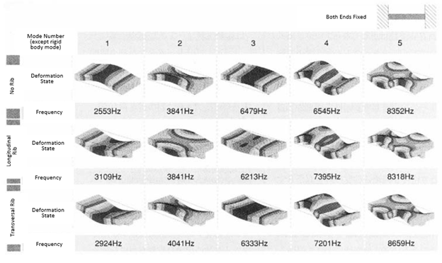
Let’s take a look at the eigenvalue analysis’s results when constraints are actually set. The same analytical model used in Fig. 1 and Fig. 3 is used, but both ends were now fixed; the results are shown in Fig. 5. These results show that the transversal rib contributes greatly to the improvement in rigidity when twisted or bent with respect to the longitudinal rib. In the third vibration mode, the highest natural frequency is obtained when there is no rib, however, but this is considered to be due to the increase of mass rather than rigidity when adding the rib.

Figure 5: Results of Eigenvalue Analysis When Both Ends Are Fixed. Fixing both ends of the plate increases the rigidity and the natural frequencies.
It is to be noted that, although there is a slight difference in the state of deformation, the bending and torsional vibration modes appear as a result of an eigenvalue analysis with free boundary conditions. Therefore, when the countermeasures for the fixed plate are taken into account, the observations gathered in the analysis under free boundary conditions can be adopted in the same manner, as Fig. 5 proves. That is, the vibrational characteristics of the designed structure can be known regardless of the constraint condition.
In conclusion, the eigenvalue analysis under free boundary conditions will show the vibration modes and effect of countermeasures, but the actual constrained model needs to be studied to clearly understand the frequencies of those modes and the deformation states.
| |
Speaker : Gabriel Roade Category : Mechanical Software : midas MeshFree Date : 2018-10-15 |

Search
Featured Resources

Structural Analysis
What Is Linear Static Analysis?
Read more >

Dynamic
Finite Element Analysis Types: The Ultimate Cheat Sheet
Read more >

Project Application
Boundary Conditions of Eigenvalue Analysis [IAD 4]
Read more >

Structural Analysis
The Future of Finite Element Analysis: MeshFree
Read more >