From the series Introduction to Analysis for Designers...
To perform most of Finite Element Analysis (FEA), a method widely used in Computer Aided Engineering (CAE), the object of analysis must be divided into one or more types of mesh. The shape is then represented as a set of simple, small and straight elements, as shown in Fig. 1, so that the shape of the object can be easily translated into the calculations.
Meshing, the process of creating such mesh, is the biggest challenge for beginning engineering analysts. Nowadays, although the number and quality of reliable automatically generated meshes is increasing, it is important to grasp the basics of meshing, because a great deal of the calculations is based on the mesh.
There are many kinds of meshes, including 2D shell meshes, 3D solid meshes, and 1D beam elements and rigid bar elements. There are also many different types of elements within the shell and solid meshes. This article will focus on describing the usual meshes generated by CAE software.
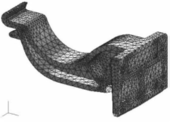
Figure 1: Mesh for Analysis
The first thing to think about before creating a mesh is what parameters want to be investigated. Stress-induced stiffness (displacement) eigenvalue determines the effort required to generate the mesh. Stiffness and eigenvalues are not so sensitive to the number of elements or the mesh shape, so they do not hinder it. Conversely, if you want to find the stress value, the mesh must be built first. Depending on the mesh, the result could be reduced to half or increased to twice the value of the correct answer.
Knowing how much results depend on the mesh, what part should you put most care on? The main characteristics of a mesh are:
First of all, in steps (1) and (2), after you have modeled the object to be analyzed, the mesh can be automatically generated by using the mesh generation function of the CAD or FEA software. At this time, many designers will use the “free mesh” function, which creates a mesh structure where nodes are not constrained to any coordinate axis, with the prospect of automatic generation in mind. Generally, the average element length throughout the object can be set in the pre-mesh stage.
The density of the mesh segmentation is determined by setting a specific, and corresponding, value. In the case of a solid, it is preferable to set the element length to about half or a third of the thickness if the object is discretized in the thickness and length directions. It is difficult, however, to set this condition as the relation between length and thickness becomes farther away from 1, that is, as the shape becomes thinner and longer, due to the increase of the number of elements. As the size of the mesh increases so does the computation time. Knowing this, how large should a mesh be?
First, consider the role of the mesh: determining the level of freedom set by the user to divide the object of analysis into elements. Creating a denser mesh results in more accurate calculated values of the stiffness of the structure, so how dense a mesh should be depends on how much accuracy the user needs.
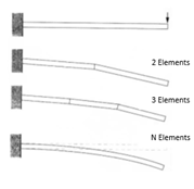
Figure 2: Element Segmentation
Consider, for example, the simple support beam problem shown in Fig. 2. A mesh density of two elements allows only one bed, while a mesh density of three elements allows only two bends. The goal is to figure out the minimum number of elements needed to accurately represent the parameters of the structure that the designer wants to calculate. The actual number of elements required for a mesh depends on the size, material, and shape of the object of analysis.
Therefore, the object must be divided into elements of different sizes at first. For example, try setting the element length in the order of 1/10, 1/20, 1/40 ~ 1/1000, and so on. Then, from the analysis results, how and when the physical quantities of interest (deformation, stress, etc.) converge is studied, as shown in Fig. 3. You do not have to do this every time, and if you have a similar scenario, you might want to use the same meshing method: dividing the element length into 1/10 ~ 1/100, 1/1000, and check how the results converge. If it does not converge, the number of ellipsoidal elements increases and the calculation time becomes too long, which is impractical.
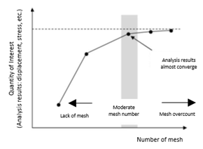
Figure 3: Valid Meshes
The limit to the number of elements in a mesh must be determined considering the performance of the computer used, the performance of the CAE software, and the allowable time for calculation. In the case of deformation or eigenvalue, it is sufficient to justify your choice, but when the stress value must be accurate, much more attention must be put into mesh division. The factor determining displacements is mainly the stiffness of the entire object, whereas in the case of stress the local condition of the portion where stress concentrates is more dominant. Therefore, it is necessary to intensely divide the areas under stress concentration into mesh segments. This is the goal of determining mesh density (2).
Most CAE software can set a localized element size, different from the average element size, for a particular area, such as the one under stress concentration. The mesh is then densely or sparsely distributed in this arbitrary region. For example, if stress is expected to concentrate in the inner surface of a curved indent, the mesh should be denser in that region, as shown in Fig. 4. Ideally, it is preferable to divide the region of interest into six equal parts. The local element partitioning system mentioned above is used here, but the degree of such partitioning is what is dependent on this specific case, and on any case. It is usually preferable to check the convergence of the stress results after meshing with a division of several degrees, such as 4, 6, 8, and so on in this example.
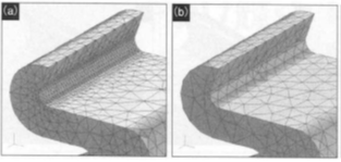
Figure 4: Mesh Density Change: (a) Subdivision of an Area with Small Radius of Curvature into Six Equal Parts. (b) Uniform Mesh Segmentation.
The overall average element size and local element size are factors that greatly affect the accuracy of the analysis, so they must be understood thoroughly. As mentioned above, since the stress value is susceptible to the mesh segmentation and element size, it is necessary to adjust these two values to obtain accurate results.
Next, let’s consider the mesh shape, or quality (3). CAE software and other mesh-generation programs have the ability of determining the quality of the mesh. The quality of the mesh determines whether the shapes formed by the elements are good or bad. There are several quantitative indices that can help you judge the quality of the mesh, such as distortion, shown in Fig. 5. This value indicates how close to a square or cube a solid element is, and how close to a square or equilateral triangle a shell element is.
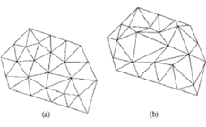
Figure 5: Mesh Accuracy: (a) Mesh with Small Distortion. (b) Mesh with Large Distortion.
The larger the value of mesh quality, the easier it is to get good results in the analysis. In particular, when calculating stress, it is necessary to confirm the mesh quality of the region of interest; not so much the farther you get from such region. If the quality of the mesh is not good enough, the worst that could happen is that the interpolator judges that the calculation is impossible to perform; each analyzer has its own evaluation criteria to determine errors that impede calculation.
If the quality of your mesh is low, it can be improved by increasing the number of elements and reducing their size. However, as mentioned earlier, the correlation between the number and size of elements and the computation time must be considered. When trying to increase the mesh quality, it is a good idea to consult a CAE expert, as it will require cumbersome work, such as reconstructing the mesh or modifying the local element geometry.
Let’s now try to understand the basics of determining the mesh degree (4). The degree of meshing refers to the accuracy of the approximate expression of the element shape. In general, a mesh has primary elements and secondary elements. Primary elements represent the displacement of the element from a vertex to another vertex, whereas secondary elements compute the displacement of the element from a vertex to a point midway towards another vertex. For example, in the case of the tetrahedral element shown in Fig. 6, the primary element has four nodes, but the secondary element has ten. Therefore, secondary elements can better represent the deformation and obtain results of higher accuracy.
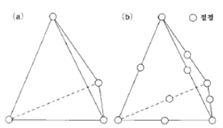
Figure 6: Primary and Secondary Elements: (a) Tetrahedral Primary Element. (b) Tetrahedral Secondary Element.
For shell elements, it is common to use primary elements. In the case of solids, tetrahedral elements are the most widely used presently, because of the difficulty of automatically generating hexahedral elements. It is also known that four-sided elements are easier to generate automatically, which can help mapping various shapes in different objects.
Before automatic mesh generation software became popular, classical cube elements were used as the main solid elements due to the fact that hexahedral elements can obtain results of high accuracy. For example, by analyzing the amount of deformation resulting on a simple support beam with hexahedral primary elements and tetrahedral primary and secondary elements, one can notice the difference in accuracy. The hexahedral primary element shows results almost identical to those obtained from the analytical solution, which does not discretize the governing equation, while the tetrahedral primary element shows results 40% below the correct values. However, the tetrahedral secondary element is only 2 – 3% below the correct values. Therefore, if tetrahedral elements are used, it is always better to use secondary elements. In fact, many CAE programs generate secondary elements from the beginning.
However, there are also some problems with using secondary elements. This is mainly due to the number of nodes. Since a secondary element has more nodes than a primary element, and the element size is smaller, the calculation time becomes longer. Attention should be paid to setting an element size in accordance with the type of element. In addition, since the edge of the element is folded at the intermediate node, the element shape is more likely to distort and the quality of the mesh to deteriorate.
Currently, the analyst does not have to worry about selecting the right element type, since most of CAE software uses secondary tetrahedral elements automatically. It is still preferable to know the difference in options.
Finally, let’s consider the possibility of mesh generation failure when trying to perform the calculation (5). When using CAE software, a message prompting that the mesh could not be generated may be displayed, or the computer may freeze during mesh generation. The main reason for these failures is the inconsistency of data due to repeated geometry changes during the design process. For example, it is difficult to generate a mesh if the original CAD data contains missing faces, micro-elements, or boundary differences between adjacent surfaces. Also, don’t forget to take tolerance into account when converting the model into the CAE software.
All these issues can affect the quality of the CAD data. If your mesh generation fails, you should check the quality of the CAD data using the Product Data Quality (PDQ) function, and go back to the CAD software and modify the data if necessary.
Once your mesh is set to go, it's time to move onto the setting of boundary conditions.
 |
Speaker : Gabriel Roade Category : Mechanical Software : midas MeshFree Date : 2018-09-24 |
Featured Resources
Structural Analysis
What Is Linear Static Analysis?
Read more >

Dynamic
Finite Element Analysis Types: The Ultimate Cheat Sheet
Read more >
Project Application
Boundary Conditions of Eigenvalue Analysis [IAD 4]
Read more >

Structural Analysis
The Future of Finite Element Analysis: MeshFree
Read more >
Keep Updated With Technical Contents


Keeping You Updated


![Comparison of Analysis Process [Infograph]](https://www.midasoft.com/hubfs/MIDAS%20-%20Blog/MeshFree%20-%20August%204th%20Week%20-%20Comparison%20of%20Analysis%20Process.png)