The number of companies introducing Computer Aided Engineering (CAE) software with 3D Computer Aided Design (CAD) capabilities is continually increasing. This allows evaluating and altering mechanical properties such as stiffness, strength, fatigue failure, thermal expansion or thermal stress by the reciprocal use of simulation and design in the initial stages of the development process. Being able to evaluate quality changes due to various characteristics of the design process allows you to find different ways of diversifying your design.
Generally, product development is carried out in the following order:
The actual development stage takes place between steps 2 and 5; in some cases, 2 – 5 are repeated many times. Being able to improve the design during the early stages of the development process gives more flexibility for changes, lowering the cost of design and product development. Since a large part of the foundation of the design is determined in stage 2, if a problem is found in stage 5, the range for improvement is more limited than if it was detected in stage 2. After testing the prototype, it takes a good deal of time and money to design, build and test any new improvements. Moreover, if the modifications do not meet the quality and cost standards, you may have to repeat these tasks several times.
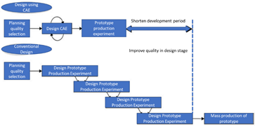
Figure 1: Shortened Development Time by CAE
If the design, however, could be evaluated at the initial stages, as shown in Fig. 1, the degree of freedom for design changes would dramatically increase, and time and cost would be reduced. That is why it is recommended to introduce CAE in the early stages of product development, allowing the evaluation of mechanical properties prior to building a prototype, by use of computer simulations. Ideally, CAE allows satisfying quality and cost goals for all parts and products through repeating design changes and evaluations, and confirming that the desired performance has been achieved.
Therefore, it is possible to construct a front-loaded development process that uses simulation to satisfy the design requirements, and then transfer the information taken from the results to later stages, as shown in Fig. 2. The automobile industry, for example, has been one of the most successful at implementing CAE. This has led to a decrease of 30 – 50% in development time over the past 20 years. Although not entirely due to CAE, large-scale crash analysis, acoustic and vibration analysis have greatly contributed to the reduction of development time and cost.
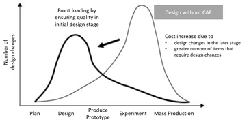
Figure 2: Front Loading with CAE
In addition, there are many companies that separate the development work between CAE experts and designers. The CAE specialist is simply a person familiar with CAE and who has excellent engineering skills and ability to judge and evaluate the designers’ intentions. However, unless there is sufficient communication with the designer, or their knowledge of the product is as thorough as the designer’s, the CAE specialist will only be able to interpret the design from and within their scope of reference. On the other hand, designers are well acquainted with the parts or products they are responsible for, and with their connection to surrounding components. They can also collaborate with the designers of other components peripheral to theirs, so as to coordinate and consult design efforts. Moreover, the designer is responsible for the initial stages of the development process: 1. Development Planning and Quality Selection, 2. Design, and 3. Design Review.
It is then preferable for designers to carry out CAE tasks so as to reduce the need for CAE specialists to make design decisions. Even in the automobile industry, where many CAE experts are needed, due to the accelerated shortening of development periods and the competition to increase quality in the initial stages of design, a shortage of CAE experts is expected. This is also due to the fact that more and more companies are establishing development structures that allow designers to analyze the design’s capabilities without the need for CAE specialists. The analysis that was previously performed by an in-house CAE specialist can now be implemented in the early design stages by the use of design-integrated analysis software.
Nowadays, CAE model development and analysis can be performed in a relatively short time to the extensive development of CAE hardware and software. Most of the recent development of CAE software for designers is focused on providing the ability to easily perform both CAE and CAD operations on a 3D model. However, despite the increase in the types and functions of software and the gradual introduction of CAE by various industries, the number of companies with designers using CAE is still small. One of the main causes is that the designer is already too busy with existing design responsibilities to be able to handle analysis tasks. Another major cause is the extent to which the CAE’s accuracy can be guaranteed by the designer; whether the designer can use the CAE correctly and find valid results.
There are two main approaches to ensure the accuracy of CAE. The first is improving the designer’s understanding of CAE; making sure the CAE method is understood and that the software can be used proficiently. The second is standardizing the method to interpret analysis results in order to avoid mistakes. Although this second approach will be effective if applied correctly, since the products and procedures at each company are different, the first approach will be examined here.
First of all, the CAE process is based on the assumption that 3D CAD software exists. This process generally has the following steps:
Particularly, the steps where designers are most likely to make a mistake are mesh division (4), the setting of boundary conditions (5), and the judgement of results (8). Most of these mistakes are due to the designer’s lack of understanding of basic CAE knowledge. If the main points behind steps 4, 5 and 8 are understood, the designer can identify erroneous parts in the calculation or parts of the model that need correction, in the case of abnormal results in the analysis.
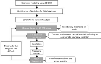
Figure 3: Interpretation Process
Regarding mesh segmentation, CAE novices often fail to recognize the fact that analytical results can vary depending on the meshing method. Slightly modifying the mesh size or the area of interest to evaluate may very well cause changes in the response simulated, so you could have set the boundary conditions and the model correctly and still get a wrong result. Because of this, meshing has been simplified considerably in designer’s CAE software. As a matter of fact, many CAE programs are equipped with an auto-mesh function, so that the designer does not have to worry about this task. The mesh is automatically re-divided according to the convergence of analysis results. However, the convenience of this features makes designers neglect valuable CAE knowledge, such as the effects of mesh size and shape.
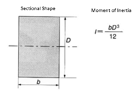
As a result, there are a lot of mistakes that arise from meshing, either automatically or manually. For example, if the mesh partition is insufficient, the stress value results after calculation may be lowered. Particularly, in the case where stress concentration at a corner is evaluated, the tendency to make mistakes is remarkable, so special care must be taken. Generally, stress is likely to concentrate in a portion with a small radius of curvature, such as the bottom of an object’s protrusion. The curvature of such corner must be divided into a sufficient number of mesh elements, and the stress value will be small unless the aspect ratio of the element shape is made as close as possible to 1. In this case, it is not reasonable to divide the whole area of the model in to a dense mesh, because most of the stress will be concentrated in these small areas of interest.
Since the amount of data increases with mesh density, and so do the computation time and display of results, sometimes becoming even impossible, a balance between must be pursued. Generally, the smaller the mesh size, the higher the accuracy; the smaller the mesh size, the more time it takes to calculate, though. Balancing practical accuracy and computation time is directly dependent on the degree of mesh partitioning and the mesh shape.
Secondly, once meshing has been resolved, one should also be aware of the setting of boundary conditions. This is specially important in eigenvalue analysis, since the setting of different boundary conditions can give you different insights of the same model. In the finite element method, if a solid element has 3 degrees of freedom in the x, y and z directions, and if a corresponding shell element is set in the x, y and z axes of rotation, 6 degrees of freedom are added to the boundary conditions. This makes the analytical model non-computable due to insufficient parameters. Many designers encounter this issue of imposing unnecessary variables. Other common mistakes include confusing unit systems when inputting a property value or the wrong selection of material. The setting of boundary conditions can also have a great impact on how heat transfers and the stresses it creates during a simulation for thermal-structural coupled analysis.
Third, it is difficult to judge analysis results without preliminary knowledge. For example, a part fixed by a boundary condition receives a total force at that boundary, so a large stress may be generated in the vicinity. However, this is an imaginary stress generated in the mathematical models for calculation purposes. If we do not pay attention to this point, it’s easy to overlook the part where the maximum stress actually occurs.
If one does not pay attention to these types of errors, the prototype will be built with flaws and the testing will fail or be inconclusive. CAE may be a panacea, but it may be poisonous as well if one step is misapplied.
In the next article of this series, we will explain the basics of CAE and common mistakes and countermeasures encountered when performing mesh generation, setting boundary conditions or interpreting results.
 |
Speaker : Gabriel Roade Category : Mechanical Software : midas MeshFree Date : 2018-09-24 |
Featured Resources
Structural Analysis
What Is Linear Static Analysis?
Read more >

Dynamic
Finite Element Analysis Types: The Ultimate Cheat Sheet
Read more >
Project Application
Boundary Conditions of Eigenvalue Analysis [IAD 4]
Read more >

Structural Analysis
The Future of Finite Element Analysis: MeshFree
Read more >
Keep Updated With Technical Contents


Keeping You Updated


![Comparison of Analysis Process [Infograph]](https://www.midasoft.com/hubfs/MIDAS%20-%20Blog/MeshFree%20-%20August%204th%20Week%20-%20Comparison%20of%20Analysis%20Process.png)