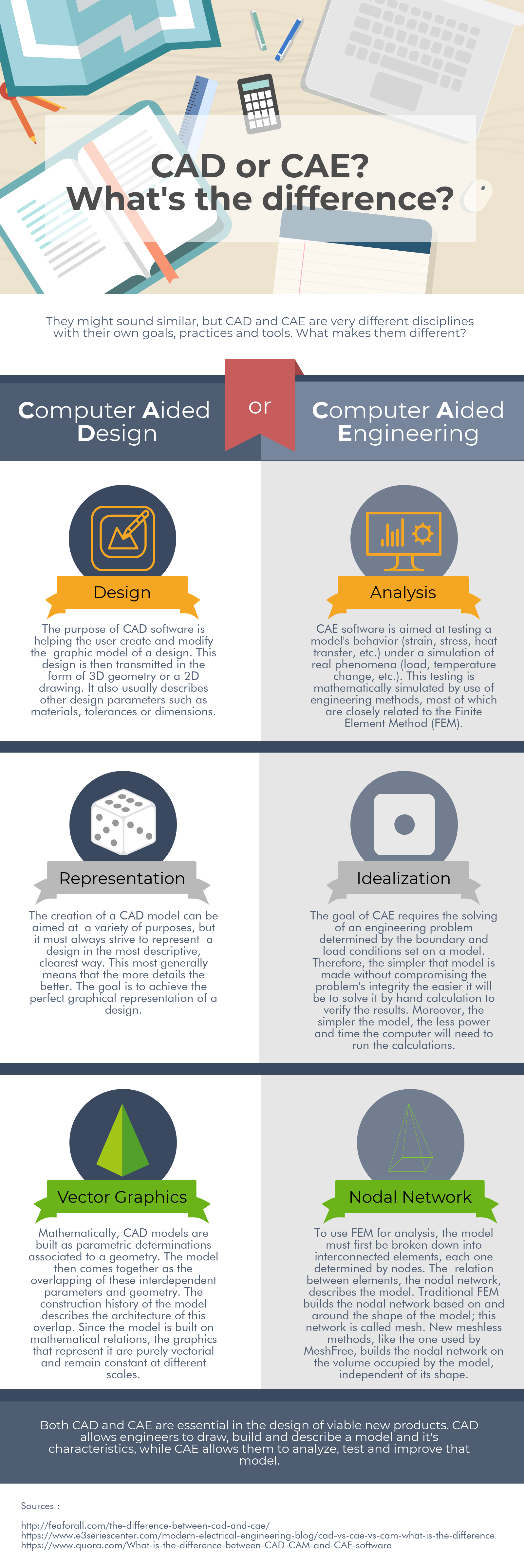
CAD or CAE? What's the difference?
They might sound similar, but CAD and CAE are very different disciplines with their own goals, practices and tools. What makes them different?

The purpose of CAD software is helping the user create and modify the graphic model of a design. This design is then transmitted in the form of 3D geometry or a 2D drawing. It also usually describes other design parameters such as materials, tolerances or dimensions.
The creation of a CAD model can be aimed at a variety of purposes, but it must always strive to represent a design in the most descriptive, clearest way. This most generally means that the more details the better. The goal is to achieve the perfect graphical representation of a design.
Mathematically, CAD models are built as parametric determinations associated to a geometry. The model then comes together as the overlapping of these independent parameters and geometry. The construction history of the model describes the architecture of this overlap. Since the model is built on mathematical relations, the graphics that represent it are purely vectorial and remain constant at different scales.
CAE software is aimed at testing a model's behavior (strain, stress, heat transfer, etc.) under a simulation of real phenomena (load, temperature difference, etc.). This testing is mathematically simulated by use of engineering methods, most of which are closely related to the Finite Element Method (FEM).
The goal of CAE requires the solving of an engineering problem determined by the boundary and load conditions set on a model. Therefore, the simpler that model is made without compromising the problem's integrity the easier it will be to solve it by hand calculation to verify the results. Moreover, the simpler the model the less power and time the computer will need to run the calculations.
To use FEM for analysis, the model must first be broken down into interconnected elements, each one determined by nodes. The relation between elements, the nodal network, describes the model. Traditional FEM builds the nodal network based on and around the shape of the model; this network is called mesh. New meshless methods, like the one used by MeshFree, build the nodal network on the volume occupied by the model, independent of shape.
Both CAD and CAE are essential in the design of viable new products. CAD allows engineers to draw, build and describe a model and its characteristics, while CAE allows them to analyze, test and improve that model.
 |
Speaker : Gabriel Roade Category : Mechanical Software : midas MeshFree Date : 2019-02-19 |
Featured Resources
Structural Analysis
What Is Linear Static Analysis?
Read more >

Dynamic
Finite Element Analysis Types: The Ultimate Cheat Sheet
Read more >
Project Application
Boundary Conditions of Eigenvalue Analysis [IAD 4]
Read more >

Structural Analysis
The Future of Finite Element Analysis: MeshFree
Read more >
Keep Updated With Technical Contents


Keeping You Updated


![Comparison of Analysis Process [Infograph]](https://www.midasoft.com/hubfs/MIDAS%20-%20Blog/MeshFree%20-%20August%204th%20Week%20-%20Comparison%20of%20Analysis%20Process.png)