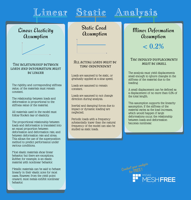
THE RELATIONSHIP BETWEEN LOADS AND DEFORMATION MUST BE LINEAR
The rigidity, and corresponding stiffness value, of the materials must remain constant.
The relationship between loads and deformation is proportional to the stiffness value of the material.
All materials used in the model must follow Hooke's law of elasticity.
The proportional relationship between loads and deformation is translated into an equal proportion between deformation and deformation rate, and between deformation rate and stress. This allows the use of the superposition method to predict performance under various conditions.
Most elastic materials show linear behavior, but there are exceptions. Rubber, for example, is an elastic material with nonlinear behavior.
Metallic materials can be said to behave linearly in their elastic zone for most cases. However, from the yield point onward, most metals exhibit nonlinear behavior.
ALL ACTING LOADS MUST BE TIME-INDEPENDENT
Loads are assumed to be static, or gradually applied at a slow speed.
Loads are assumed to remain constant.
Loads are assumed to not change direction during analysis.
Inertial and damping forces due to impact or dynamic loading are neglected.
Periodic loads with a frequency substantially lower than the natural frequency of the model can also be studied as static loads.
THE INDUCED DISPLACEMENTS MUST BE SMALL
The analysis must yield displacements small enough to ignore changes in the stiffness of the material due to the loading.
A small displacement can be defined as a displacement of no more than 0.2% of the total length.
This assumption supports the linearity assumption. If the stiffness of the material varies as the load increases, which would happen if large deformations occur, the relationship between loads and deformation becomes nonlinear.
What you need to know
Any interaction that will change the motion, direction or structure of an object is considered a force.
A force can cause an object with mass to accelerate, to deform, or to accelerate and deform simultaneously.
A force is a vector quantity, with magnitude and direction, and it can be measured in the SI unit of Newtons. It is usually represented by the symbol F.
The magnitude of a force can be calculated as the product of the object’s mass and acceleration.
When not applied on an axial direction, a force can cause twisting or bending. These twisting and bending forces are referred to as moments. At a specific point, the moment caused by a force is equal to the product of the force’s magnitude and the distance between the point studied and the point where the force is applied.
In solid mechanics, the external forces acting on a structure and causing deformation or damage are defined as loads.
To ensure safety of a designed product, the loads expected to act on the product must be defined for analysis.
Loads can be categorized into static and dynamic loads depending on whether they change over time or not. The own weight of a structure is an example of static load. Impact loads caused by sudden acceleration or deceleration of equipment, or a motor spinning at a certain rpm, are categorized as dynamic loads.
The main loads used in analysis are the own weight of the structure, dead and live loads, pressure loads, temperature loads, wind, seismic loads, and vibration and impact loads.
The third of Newton’s Laws of Motion states that all forces occur in pairs such that if one object exerts a force on another object, the second object will exert an equal and opposite reaction force on the first.
In general, reaction forces appear at the point of constraint, and in the direction in which the motion of the structure is restricted.
The sum of external forces, or loads, and the sum of reaction forces have the same value, but act in opposite direction.
Reaction forces are used as important data in the design of supports.
Since loads and reaction forces have the same value and act in opposite direction, the overall structure has no motion. Therefore, if a cut is made at any point in a structure, the resulting parts should also have no motion. The forces acting within the cut cross section are defined as internal forces.
In accordance with Newton’s Third Law of Motion, the sum of loads and reaction forces on each cut part and the sum of internal forces on that part have the same value.
Generally, internal forces divided by cross section are defined as stress.
Stress refers to the internal force per unit area. It is mathematically expressed by the following equation, where F is the force and A the area:
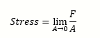
Since internal force is a vector having a magnitude and direction, stress is also defined as a vector physical quantity.
The stress acting on a face placed in any direction can be divided into components acting parallel and perpendicular to the face.
Normal stress is the stress acting in a direction perpendicular to a face.
Shear stress is the stress acting in a direction parallel to a face.
Changes in the spatial position of a structure are collectively defined as displacement.
Displacement is not necessarily accompanied by deformation; a representative example would be rigid body motion.
Rigid body motion is a type of behavior wherein the position of an object in space changes through translation and rotation only, with no change in the relative distance between two points in the object.
Deformation refers to a change in the external shape of a structure.
When deformation occurs, all points within an object, or all points except for some points, are displaced, and the relative distance between two points changes.
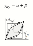
Strain is categorized into normal strain and shear strain, and it is a dimensionless quantity.
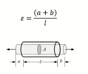
Normal strain expresses the degree by which an object stretches or shrinks in a certain direction. It is mathematically defined as the increase in length in the axial direction of an object (a+b) divided by the original length of such object (l). It can be expressed in the form of this equation:

Shear strain expresses the degree to which an object is crushed. It is defined as the change in angle, measured in radians, between two edges that form a right angle:
The stress-deformation rate relationship is the most important characteristic in defining the dynamic behavior of a material. It can be defined through the tensile testing of the material.
If the stress is plotted against the deformation, the graph would look like this:
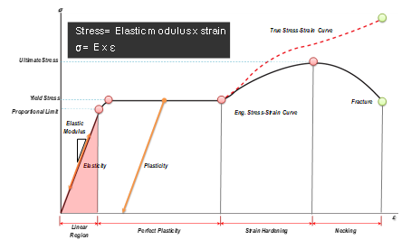
The zone wherein the material returns to its original shape after the acting load has been removed is defined as the elastic zone of the material. In this zone, stress and deformation have a linear proportional relationship. The value of the slope in such linear relationship is called the elastic modulus (E), and the relationship between stress and deformation can then be expressed as:

The zone wherein the material cannot return to its original shape even after the acting load has been removed is defined as the plastic zone. Here, it is said that permanent deformation has occurred and that the material has yielded.
The boundary between the elastic and plastic zones is called the yield point. The stress at this point is defined as the yield stress.

The value of the stress at the point where fracture starts to occur is referred to as the ultimate stress.

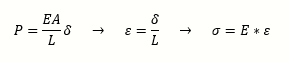
The ultimate purpose of solid mechanics is finding out how much deformation occurs in a designed product depending on its shape and its material characteristics.
Therefore, if the deformation (δ) caused by a load (P) can be calculated using the area (A), the original length (L) and the elastic modulus (E), such deformation value can then be used to calculate the strain (ε). From the strain, the stress (σ) is then computed.
Learn about other kinds of analysis in our Finite Element Analysis Ultimate Cheat Sheet!
 |
Speaker : Gabriel Roade Category : Mechanical Software : midas NFX Date : 2018-08-27 |
Featured Resources
Structural Analysis
What Is Linear Static Analysis?
Read more >

Dynamic
Finite Element Analysis Types: The Ultimate Cheat Sheet
Read more >
Project Application
Boundary Conditions of Eigenvalue Analysis [IAD 4]
Read more >

Structural Analysis
The Future of Finite Element Analysis: MeshFree
Read more >
Keep Updated With Technical Contents


Keeping You Updated


![Comparison of Analysis Process [Infograph]](https://www.midasoft.com/hubfs/MIDAS%20-%20Blog/MeshFree%20-%20August%204th%20Week%20-%20Comparison%20of%20Analysis%20Process.png)