


In the FEM, the most critical question is “how many meshes do we need to get the correct (or reasonable) results?”

2 min read
Author: Seungwoo Lee, Ph.D., P.E., S.E.
Publish Date: 24 Oct, 2022
The scary part of FEM is sometimes FEM gives wrong results without any error message. The analysis may be meaningless if an engineer cannot check or interpret the results. Let’s consider a simple example similar to the case from Dr. Gallagher (Finite Element Analysis: Fundamentals, 1975).
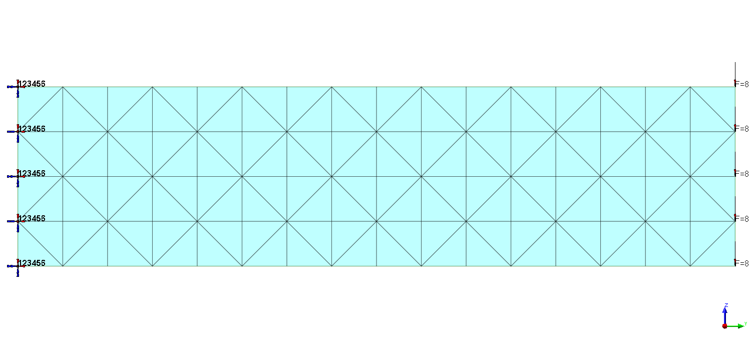
The structure is L = 48 in. cantilever beam, and the section is 1 in. × 12 in. rectangular section. Assume E = 30,000 ksi and ν = 0.25. The load is 40 kips point load at the cantilever tip. Our question is about the deflection at the cantilever tip and the stress at the top of fixed-end support.
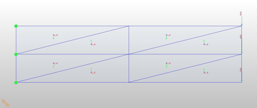
Let's start with the simplest element, triangular elements.
Geometry, Two triangular element case
The computer gave us deflection = 0.0249 in. and stress = 1.804 ksi.
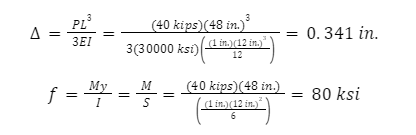
Luckily, we can perform this analysis by hand. Neglecting the effects of shear deformation, the deflection and stress shall be close to
|
Deflection (in) |
Stress (ksi) |
|
|
Beam theory |
0.341 |
80 |
|
Two triangular element |
0.0249 |
1.804 |
|
128 triangular element |
0.306 |
66.85 |
|
1152 triangular element |
0.350 |
86.55 |
|
2 high-order triangular element |
0.285 |
50.73 |
|
32 high-order triangular element |
0.355 |
81.94 |
|
1 quadrilateral element |
0.269 |
40 |
| 1 plate element |
0.341 |
80.22 |
As can be seen, these two values are not even close and one may be correct and one may be wrong.
Q) Which is correct and which is wrong?
A) Results from beam theory are correct but results from FEM are wrong.
Q) Why are FEM results wrong?
A) That is the limitation of the simple triangular element. In this element, it is assumed that the strain is constant with an element. In other words, if the material is homogeneous, like in this example, the stress is constant within an element since stress = modulus of elasticity × strain, f = Eε. Since the stress is constant within the upper element, the top and bottom stress at the fixed support are the same in this example, which cannot be.
Q) How about increasing the number of elements?
A) Let’s try 16×4 = 128 elements. The computer gave us deflection = 0.306 in. and stress = 66.84 ksi. The deflection looks reasonable, but the stress is still way off.
Geometry, 128 triangular element case
Stress (ksi), Two triangular element case
Most commercial programs have the option to calculate averaged stresses at each node and show continuous stress contours using regression techniques.
Averaged stress (ksi), Two triangular element case
Believe it or not, these averaged stresses at each node are not simple average values but more reliable stresses than the stresses at each element. Mathematically these averaged stresses are “one order higher” than the stresses at each element.
However, in this example, there are huge differences between adjacent elements (66.84 ksi and 32.2 at the left top elements, almost twice), and the stresses are unreliable.
- Q) OK, Let’s try more elements, say 100,000 elements.
- A) We can do that because now we have powerful computers. But before increasing the number of elements, we must think about some more things.
The minimum element length is 3 in., and the length/thickness ratio is around 3. This is already beyond the limit of the thin element. The mathematical meaning of “thin” is rather complicated and need not be discussed here in detail. However, we should remember that it is always a good practice to limit the length/thickness ratio above 5. (Of course, there are also “thick” elements, but they won’t be discussed in this article.).
This structure has a very simple geometry, and it is normally more than enough if we have ten divisions in the longitudinal direction and four divisions in the vertical direction. If we cannot get reasonable results with these 10×4 meshes, it is better to consider other options, which will be discussed in the next article.
We have more critical questions. In this example, we know the correct (or without contradiction) results. However, in most engineering problems, we do not know the correct results. If we knew the correct results, we do not need to perform FEM. In this case, how do we know whether the given results are correct or wrong?
Add a Comment