To ensure stable analysis performance and reliable result approximation, meshing is important. Meshing is the process to create finite eleme...

4 min read
Author: JC Sun
Publish Date: 28 Dec, 2021
- Keep Running into Analysis Errors When Everything Looks Right?
It’s not uncommon for the analysts to run into the same analysis error after having checked the analysis set up a hundred times. It’s also common to find a nonlinear analysis not able to reach convergence after it has worked out perfectly in the linear domain. Most likely the issue is within meshing. Meshing and meshing control is an important step in FEM analysis, and computed FE results tend to be the most accurate when elements are compact, without great elongation, skew, or warping [1].
- What Causes Distorted Elements?
Element distortion can happen when portraying geometric irregularity. Using more compacted elements and finer mesh at those locations can help with improving the result accuracy. However, it’s not economical to use the same fine mesh throughout the geometry, because coarser meshes are sufficient to represent the geometrically simpler parts of the model. Coarser mesh is also sufficient when the load application is far enough from the geometry and the expected corresponding stress effect is trivial and causes insignificant deformation. Therefore, for models that have both fine and coarse meshes, element distortion can happen due to the mesh size transition. Figure 1 shows the distorted elements highlighted in green due to the transition from coarse to fine elements.
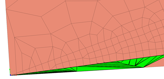
Figure 1. Distorted elements (highlighted in green) due to the transition from coarse to fine elements
Element distortion can also happen due to the connection between mesh sets. In FEM, object connectivity is utilized using nodal connectivity. Therefore, the simplest way to model two connecting objects is to merge the nodes at their connecting boundaries. However, when two mesh sets have different mesh sizes, the transition of mesh elements is needed.
- How to Check Element Quality?
Besides element distortion, the relative size between connected elements and the shape and quality of a mesh has a larger effect on the analysis results than its absolute size. Hence, after creating a mesh, it is important to check and modify the quality of the mesh.
Aspect Ratio
Aspect ratio is the length ratio between the width and length or the ratio of the longest side to the shortest side of a 2D element. For example, a square has the same width and length and therefore has an aspect ratio of 1. As a shape digresses from the square shape, the aspect ratio becomes smaller. A value closer to 1 is ideal. This ratio has a significant effect on the analysis result in and if the value is very small, it may be hard to obtain normal analysis results.
Skew Angle
Skew angle describes how much the shape digresses from the rectangular shape (90 degrees), measured in angles. A quadrilateral forms a 90-degree angle, the inclination angle is 0 degrees, and this value increases as the shape strays from the quadrilateral. For a solid element, the inclination angle is checked for each face and the smallest value is chosen as the inclination angle. A value closer to 0 is better. Figure 2 shows the skew angle of triangular and quadrilateral elements.
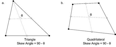
Figure 2. Skew angle calculation of triangular and quadrilateral elements in Midas FEA NX.
Warpage
Warpage evaluates how much the shape is out of the plane. For a quadrilateral 2D element with all nodes on the same plane, the value is 0. The value increases as the shape strays from the plane. For a solid element, the warpage is checked for each rectangular face and the smallest value is chosen as the warpage value. A value closer to 0 is better. This item has a significant effect on the analysis result and if the value is very large, it may be hard to obtain normal analysis results. Figure 3 shows how the warpage value is calculated.
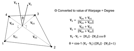
Figure 3. Warpage value calculation for 2D quadrilateral elements in Midas FEA NX.
Taper
Taper calculates geometrically how much the quadrilateral digresses. It is not applied to triangular elements. A quadrilateral has a value of 1, and the value decreases as it digresses, meaning that it becomes closer to a triangular shape from its rectangular shape. For a solid element, the taper value is checked for each face and the smallest value is chosen as the taper value. A value closer to 1 is better. Figure 4 shows how the taper is calculated.
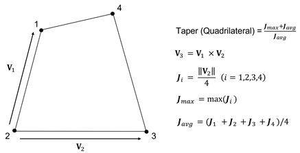
Figure 4. Taper value calculation for 2D quadrilateral elements in Midas FEA NX.
Jacobian Ratio
The Jacobian determinant is calculated at each Gauss integral point on the mesh. The Jacobian ratio is the ratio between the largest and smallest Jacobian determinant value. For 2D elements, the Jacobian determinant is calculated on the element projected onto a plane. For solid elements, the Jacobian determinant is calculated directly. If the quadrilateral element is not convex, the negative value is outputted, and the analysis is not performed properly. A higher Jacobian ratio value is better.
Twist (solid)
The value represents the twist between 2 opposing faces in a solid.
For the 6 conditions above, Midas FEA NX does an automatic check and highlights the elements that do not satisfy the user input criteria.
- How to Prevent Element Distortion?
Mesh control is used in FEM software for users to define the nodal location and mesh size. For example, engineers can specify the size of elements surrounding the selected point, as shown in figure 5.
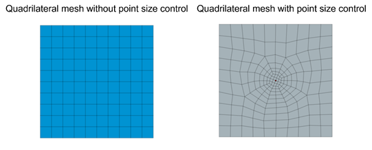
Figure 5. Mesh control using point size control in Midas FEA NX.
Engineers can also specify the seed size at a particular edge, shown in figure 6. This is particularly helpful at the connection boundary of the mesh bodies with different element sizes.
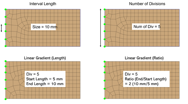
Figure 6. Mesh control using various edge size control methods in Midas FEA NX.
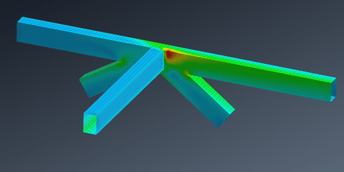
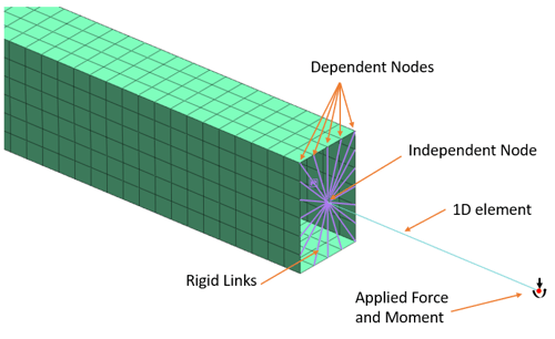
There are also instances where the fine mesh is needed around locations of structural interests. For example, large displacement and stress variation is expected around where the load is applied, or the moment might be high along part of the bridge girder from the general beam element analysis. It is more economical and time-saving to only apply fine mesh around the said regions while representing the rest of the structure using coarse mesh. Edge mesh control can be implemented to connect the coarse mesh to the fine mesh, which implements merged nodes at the mesh set boundaries and a smooth element size transition to prevent distorted elements. Figure 7 and figure 8 show two examples of mesh size transition from coarse to fine mesh while ensuring element quality for better analysis results.
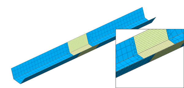
Figure 7. Mesh transition between fine and coarse mesh utilizing edge seeds control on a steel tub girder plate element mesh.
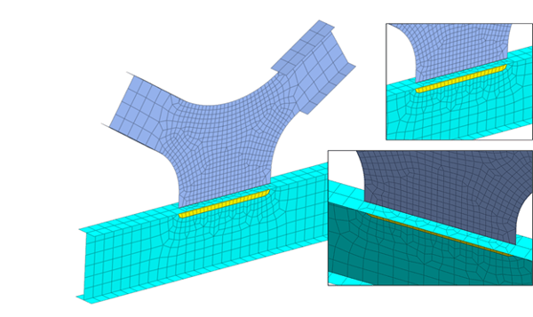
Figure 8. Mesh transition at I girder connection utilizing edge seeds control to ensure merged nodes at mesh sets boundaries.
References:
[1] Cook, Robert D., Malkus, David S., Plesha, Michael E., Witt, Robert J., Concepts and Applications of Finite Element Analysis, Fourth Edition, 2001, John Wiley & Sons Inc., New York, NY.
https://www.midasoft.com/bridge-library/civil/products/midasfeanx

Add a Comment