I girder vs. tub girder Our next question may be “What are the differences between an I and a tub girder?”
3 min read
Author: Seungwoo Lee, Ph.D., P.E., S.E.
Publish Date: 25 Sep, 2023
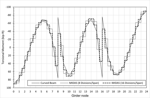
The previous article (Curvature effects on a medium-span curved bridge) showed that we should be cautious to get reasonable torsional moments through simple beam analysis. One of the easiest ways to refine the results is to add more nodes at the inner support locations, however, we still have a question about “how many?”. Now we are reviewing the effect of curvature for bending moments.
We are trying to find bending moments for three spans continuous curved girder, 150
ft + 223 ft + 150 ft = 523 ft, the radius is 1182’-6” as shown.
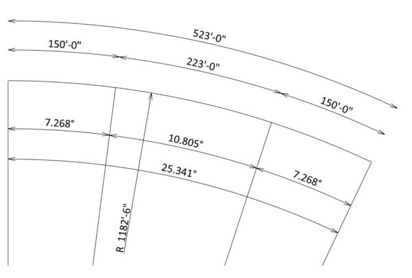
Fig1 Basic Geometry
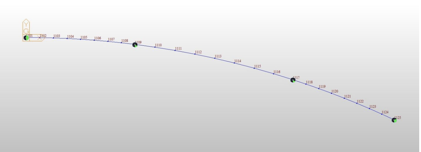
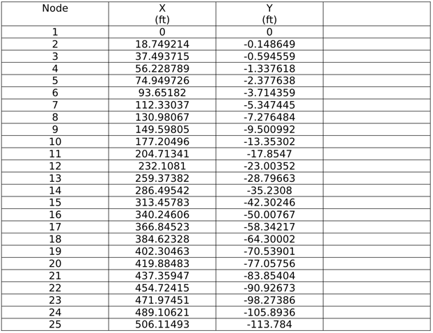
Since the girder is curved, we cannot model this bridge with a single element between supports and we need some additional nodes. Again, we have a question about “how many?”. For whatever reason, we will divide each span into eight elements. If we assume the beginning node as (0,0), the nodal coordinates can be.
Curved Girder Analysis - Nodal Coordinates
Curved Girder Analysis - Midas model views
Fig2 Midas model plan view
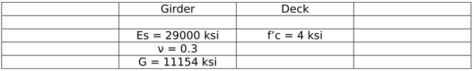
Material property and typical section are,
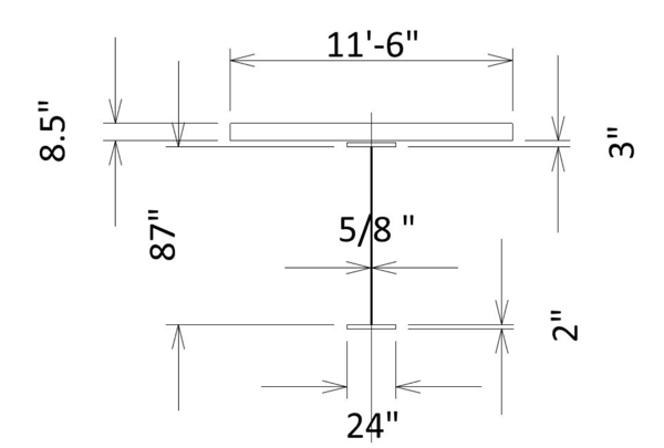 Fig3 Typical section
- Material property
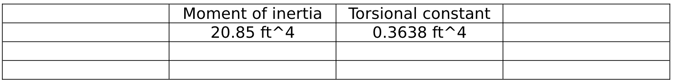
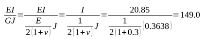
The calculation of the moment of inertia for the horizontal axis is very straightforward. However, there may be many arguments about how to calculate the transverse moment of inertia and torsional constant. With whatever assumptions, torsional constants are calculated as below.
- Section property
In the straight girder analysis, the torsional constant has little effect on the analysis, however, this is not the case for curved girders.
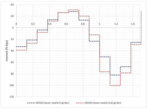
For this I girder bridge, the effect of torsional constants is not major, however, for box girder bridges, the story shall be totally different. For comparison purposes, let’s analyze for constant uniform loads 1 kip/ft.
.png?width=672&height=490&name=Curved%20girder%20analysis%20Moment%20diagram%20(ft-kips).png)
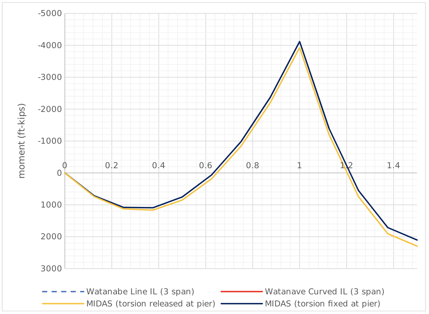
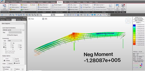
The moment diagram is shown in Fig 4 and the maximum negative moment at the pier location is M=-3925 ft-kips.
- Maximum negative moment comparison (ft-kips)
![]()
%201.png?width=672&height=84&name=curved%20Girder%20Analysis%20Maximum%20negative%20moment%20comparison%20(ft-kips)%201.png)
To check these results, compare this diagram with that from the linear girder analysis. There are some ways to analyze a linear girder, but the method from Dr. Watanabe is one of the easiest to implement (previous article, Influence line analysis for continuous girders). As discussed in the previous article, Watanabe’s method required only one input, span length ratio 233/150=1.49, and very easy to check this one input! Watanabe’s solution gives the exact solution (other than considering the effects of shear deformation which is negligible for most practical bridges).
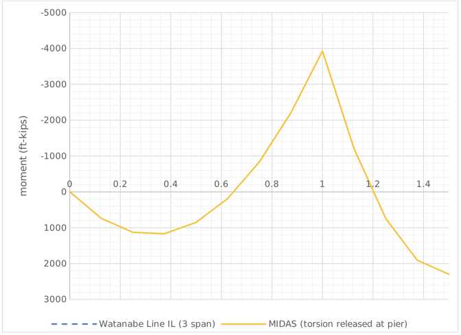
Fig6 Moment comparison
From Watanabe’s methods, the maximum negative moment at the pier location is M=- 4033 ft-kips and the difference from the MIDAS result is around 3%. If you have the hawk’s eyes, you might have caught that the support condition at the pier is just vertical support (Fig2). In other words, the girder can twist freely at
inner supports. This condition is rarely met in the real world. If we have two bearings at each girder (used to be a common practice in the traditional box girders), the support condition is close to torsional fix, or even if we have one bearing at each pier, the support condition is somewhere between torsional free and torsional fix due to the effects of pier diaphragm. MIDAS model has to include these conditions to compare the results with Dr. Watanabe’s. The updated model view is as below (Dr. Watanabe has developed a very detailed solution both for torsional free and torsional fix condition, but the torsional fix condition is adopted in this article).
inner supports. This condition is rarely met in the real world. If we have two bearings at each girder (used to be a common practice in the traditional box girders), the support condition is close to torsional fix, or even if we have one bearing at each pier, the support condition is somewhere between torsional free and torsional fix due to the effects of pier diaphragm. MIDAS model has to include these conditions to compare the results with Dr. Watanabe’s. The updated model view is as below (Dr. Watanabe has developed a very detailed solution both for torsional free and torsional fix condition, but the torsional fix condition is adopted in this article).
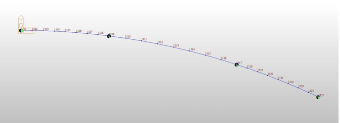
Fig7 Plan view (at pier location, girder twist is restrained) From this updated model, the maximum negative moment at the pier is M=-4117 ft-kips and the differences between torsional free and fix are around 5%. As expected, the results from this model give a little closer result (2% error) than those from the torsional-free condition (3% error).
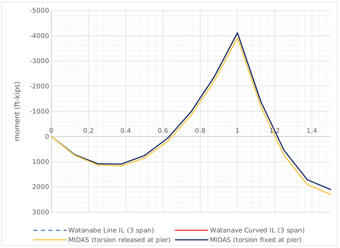
Fig8 Moment comparison
Curved Girder Analysis - Closure
The analysis of curved girder systems is challenging. Using programs, we can get results without any understanding of basic curved beam theory. However, to get the correct/reasonable output is not that simple. It has been strongly recommended to start with a simple straight-beam model before starting a fancy 3D model. The 3D model gives more accurate results, but this is only the case if our input and analytical theory are correct. Not many programs have the curved beam elements and without these elements (not easy to implement into multi-purpose commercial programs), our analysis only estimates anyway. Other than extreme cases, the moment from straight beam analysis gives reasonable values and is good for a start and for comparison, at least. However, if we need torsion moments from the analysis, straight beam analysis is not enough, and we do need more refined techniques.
Add a Comment