The previous article (Curvature effects on a medium-span curved bridge) showed that we should be cautious to get reasonable torsional moment...
3 min read
Author: Seungwoo Lee, Ph.D., P.E., S.E.
Publish Date: 21 Feb, 2021
What is Convergence? What is a Convergence Study?
It is easy to obtain the result from bridge finite element analysis, but to get more accurate results requires extra effort. Even the most robust finite element analysis solvers adopt the method that approximates the structural behavior, by minimizing the associated error function compared with the complex function that represents the realistic structural behavior.
To make this approximation more accurate, convergence studies need to be done, Typically, convergence refers to the smallness of the elements required in a model to ensure that the results of an analysis are not affected by changing the size of the mesh (The importance of Mesh Convergence, NAFEMS). Convergence study is an iterative process in which the mesh size is refined until the finite element analysis results are within a stable and reasonable range, and further refinement of the mesh size does not affect analysis results.
Why is Convergence Important in Curved Girder Analysis?
Let's start with an example. To obtain torsional moments in the curved girders from the bridge shown in Figure 1, the bridge is modeled in midas Civil using 1D elements. The bridge has spans of 160 ft - 210 ft - 160 ft measured along the centerline of the bridge. The radius of the bridge is 700 ft at the centerline. All supports are radial with respect to the centerline. Four I girders run along the bridge span, and detailed dimensions and properties can be found in the reference.
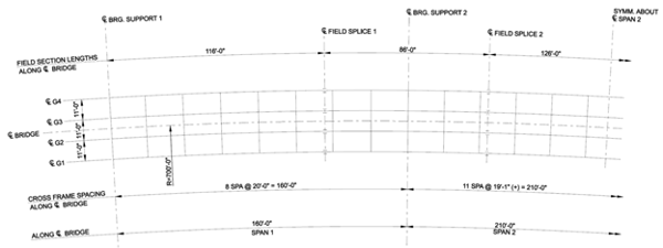
Figure 1. Framing plan of a typical three-span continuous horizontally curved composite steel I-girder bridge (FHWA-IF-12-052 - Vol 23, pg. 13)
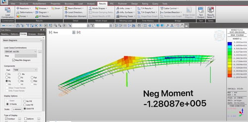
We are modeling G04, the longest girder, as a single-line girder. We divide each span with equally spaced eight elements. The given loading is uniform loads as shown in figure 2, and the torsional moment diagram output is shown in figure 3. (Download the input file: 8Division).
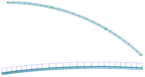 Figure 2. (Top) Plane view and (bottom) general view with loading and boundary condition.

Figure 3. Torsional moment due to uniformly distributed load for curved girder G04.
As shown in Figure 3, maximum torsional moments occur at the girder ends where the abutments are. However, torsional moments are relatively low at the pier locations. At the center span, maximum torsional moments occur somewhere near the quarter points. 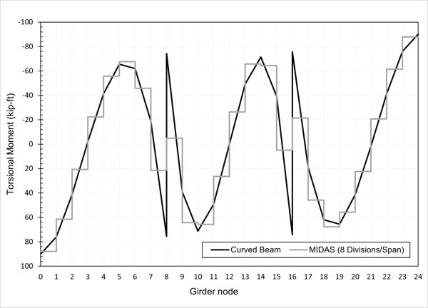
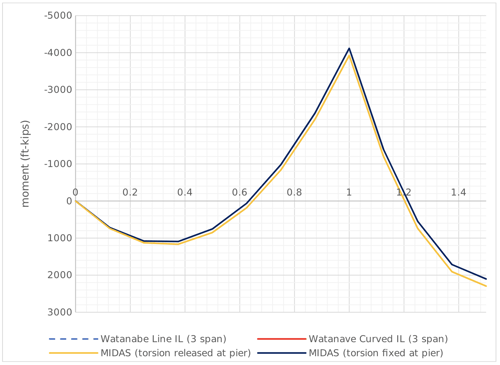
Figure 4. Torsional moment comparison (1 of 2).
The graph in Figure 3 is re-generated in Figure 4 with the grey line. The black line is the torsional moments from classical curved beam theory (Watanabe. N. 1967, Theory and Calculation of Curved Girder, Gihodo, Tokyo). Figure 4 shows the difference in the torsional moments using two methods at the pier location (nodes 8 and 16) is significant. From the classical theory, the torsional moment at node 8 is around 76 kip-ft to -74 kip-ft. However, the value from midas Civil is around 22 kip-ft to -5 kip-ft.
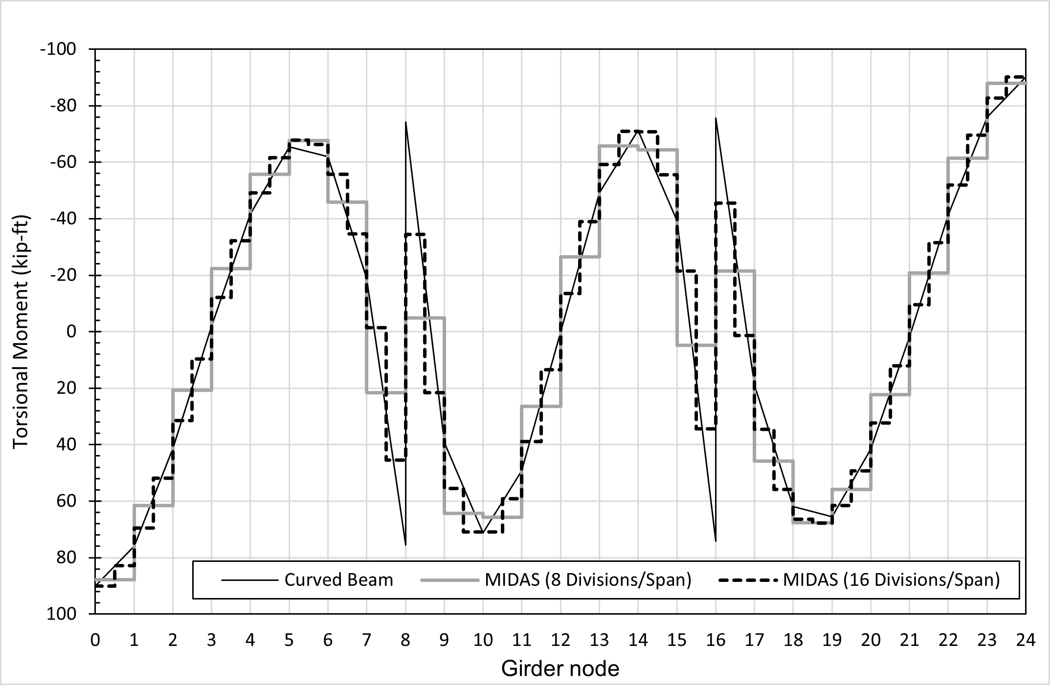
This difference is because 1) Curved girders are modeled using straight beam elements, 2) Most programs, including midas Civil, assume the torsional moment within an element to be constant. When we look at elements 8-9, where T = -5 kip-ft is close to the average of the torsional moment from classical theory, (-74 kip-ft + 39 kip-ft)/2. Since modeling the curved girder using curved elements is not possible, we can try to refine the size of the straight beam elements used to simulate the girders. As shown in Figure 5, the torsional moments obtained from reducing the beam element size by half are compared with those from Figure 4. (Download input file: 16Division).
 Figure 5. Torsional moment comparison (2 of 2).
From the outlook, the output from the model with more refined curved girder elements has a better resemblance with the theoretical behavior. If we divide each span into 16 elements, midas Civil gives the torsional moments as 46 kip-ft to -34 kip-ft at node 8. Even though this is still not close to the "real" solution, reducing the element size by half has made the result approximation much closer than previously.
Then how do we know the ideal element size? Do we increase the number of divisions to 32, 64, or even 100? Going back to our original question: why is convergence study important in curved girder bridge analysis? A convergence study is able to help determine when to stop refining element size for the straight beam elements. The formal method of establishing mesh convergence requires a curve of a critical result parameter in a specific location (The importance of Mesh Convergence, NAFEMS), in this case, the parameter could be the torsional moment value at element node 8-9. By plotting the mesh refinement against the torsional moment, a general trend can be observed and engineers can decide what mesh refinement is that no longer affects the analysis result.
Editor: JC Sun
jsun@midasoft.com
Add a Comment