The previous article (Curvature effects on a medium-span curved bridge) showed that we should be cautious to get reasonable torsional moment...
2 min read
Author: Seungwoo Lee, Ph.D., P.E., S.E.
Publish Date: 3 Oct, 2023
I girder vs. tub girder
Our next question may be “What are the differences between an I and a tub girder?”
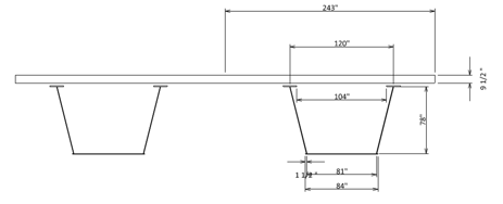
Fig1 Section view for a typical tub girder
Fig 1 shows a section view for a typical three-span continuous tub girder bridge. The moment of inertia and torsional constant are as follows. Again, there have been many arguments about torsional constant calculation.
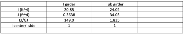
Even though we do not know the exact value of torsional constants, we can see that the ratio (149.0)/(1.835)=is around 80 and worth remembering.
.png?width=497&height=365&name=Moment%20comparison%20(exact%20solution).png)
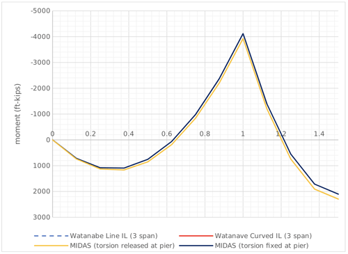
Fig 2 Moment comparison (exact solution)
From Fig 2, we can see that the moment diagram for a tub girder is close to that of a straight girder, however, there are some differences between the tub and I girders. For a tub girder, the torsional rigidity is relatively large, and the rotational twist is restrained. In other words, the effects of curvature are not that major for a tub girder bridge.
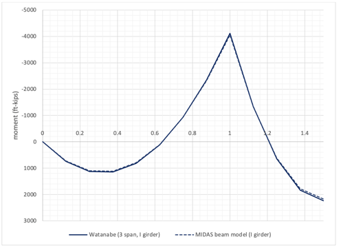
Fig3 Moment comparison for a curved I girder
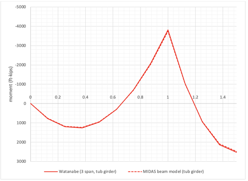
Fig4 Moment comparison for a curved tub girder
Fig 3 and Fig 4 show that MIDAS gives very close results compared to the exact solution both for I and tub girders. In other words, we can use MIDAS output both for I and tub girders in the case of the moment design with reasonable element divisions.
.png?width=510&height=376&name=Moment%20comparison%20(MIDAS).png)
Fig 5 Moment comparison (MIDAS)
Fig 5 shows moment comparisons for I and tub girders from MIDAS. Fig 5 is close to Fig 2 and again we can see that the MIDAS’ results with kinked members are very close to those from curved elements.
However, the story may be somewhat different for torsional moments.
.png?width=510&height=374&name=Torsional%20moment%20comparison%20(exact%20solution).png)
Fig 6 Torsional moment comparison (exact solution)
Fig 6 is the torsional moment comparison between I and tub girders. Fig 6 clearly shows the effects of torsional rigidity and torsional support. For I girders (blue line), the torsional rigidity is relatively low, and we can see that the torsional moments are not continuous at inner supports. In contrast, the effects of inner supports are relatively minor for tub girders because the torsional rigidity is relatively high. In other words, the effects of torsional supports are not significant for tub girders, and we may not need any cross frames for tub girders.
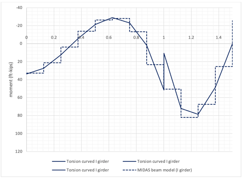
Fig 6 Torsional moment comparison for a curved I girder
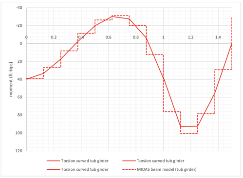
Fig 7 Torsional moment comparison for a curved tub girder
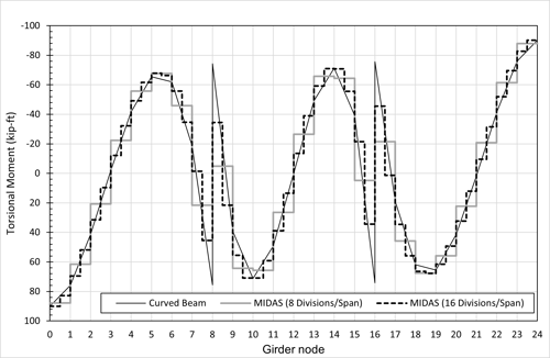
Fig 6 and Fig 7 show the torsional moment comparison between the exact solution and MIDAS. MIDAS’ results show somewhat similar trends with those from the exact solution, but the values are way off at some locations. The curvature of this example is rather minor (R=1182.5ft), and these effects would not be minor for high-curvature bridges.
.png?width=499&height=367&name=Torsional%20moment%20comparison%20(MIDAS).png)
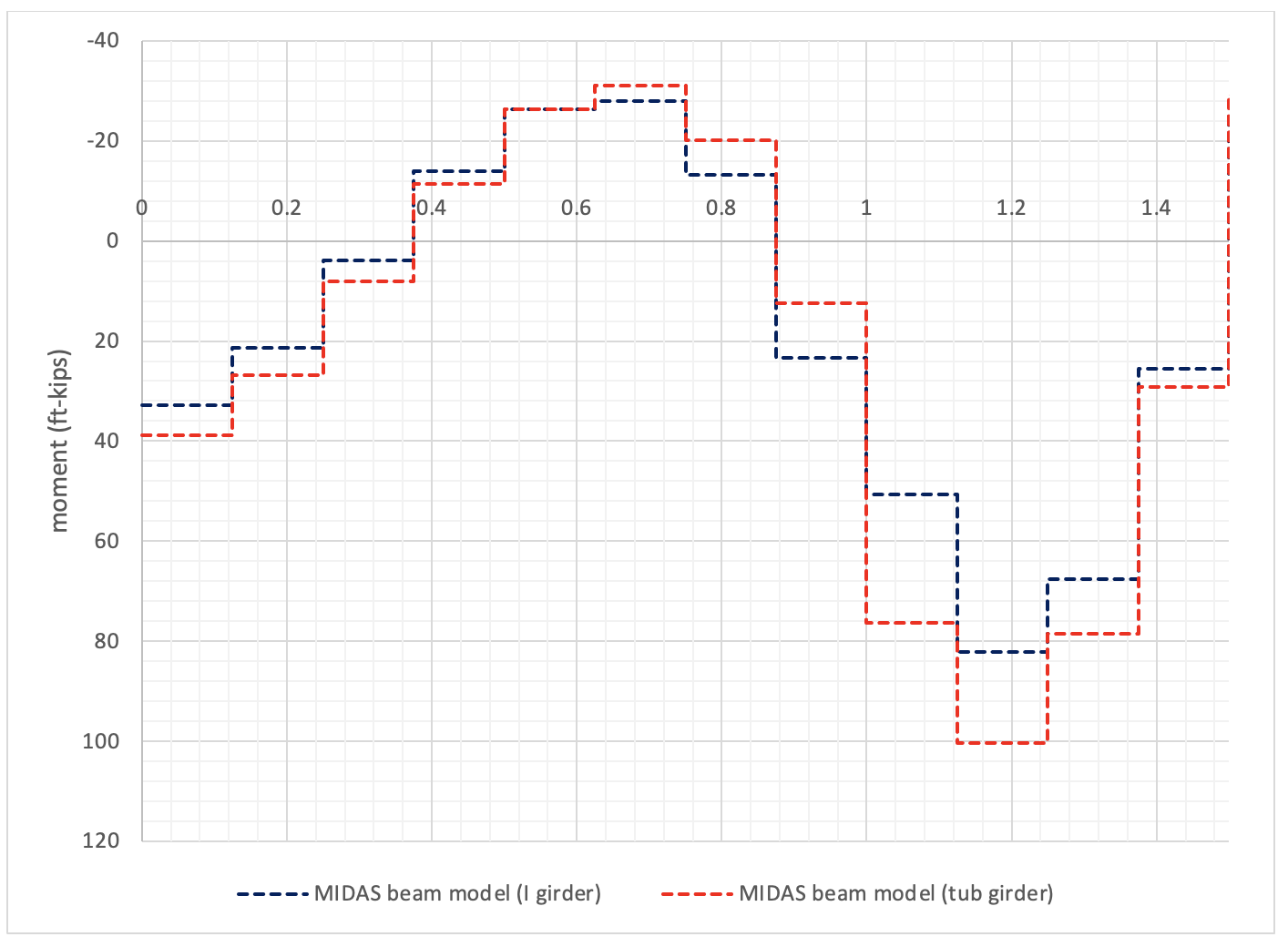
Fig 8 Torsional moment comparison (MIDAS)
Fig 8 shows the torsional moment output from MIDAS. It may not be easy to drive the true torsional moment Fig 6 from these MIDAS outputs. We may need some tools to check the torsional moment from computer output for curved girders.
Add a Comment