In this Intro Session our MIDAS engineer explained about Midas FEA NX's capability in simulating structural connections such as contact, wel...
4 min read
Author: JC Sun
Publish Date: 26 Jan, 2022
In the previous blog basic finite element mesh explained, we have looked into several types of conventional elements within the 1D, 2D, and 3D realms. We also explained briefly the pros and cons of each type of element and its applications in finite element analysis. In this blog, we are going to talk about two types of special-purpose elements available in MIDAS analysis software.
-
What are Links in Finite Element Analysis?
Links are created by connecting 2 nodes together, just like the way we create any other 1D elements. However, it is not a 1D element and behaves differently from truss and bar elements. Links do not have structural properties, such as unit weight, Poisson’s ratio, etc. However, elastic links can have stiffness in displacement and rotational stiffness in each axial direction. Elastic links can be used to simulate elastomeric bearings and establish simple contact. Rigid links can be used to connect mesh sets of different dimensions.
- What are the Types of Links?
-
- Elastic Links
Generally, elastic link elements are composed of displacement and rotational stiffness in each axial direction. Elastic links can be in the form of tension-only and compression-only links. In tension-only links, the elastic link only has stiffness in tensile direction, meaning when compression happens the stiffness becomes nonexistent, vice versa for compression-only links. Elastic links can be appropriately used for elastomeric bearings that connect the top and bottom piers of bridge structures and for ground boundary conditions that have compression-only properties. In the blog elastomeric bearings for bridges, you can read more about elastic links applications to simulate elastomeric bearings.
-
- Rigid Links
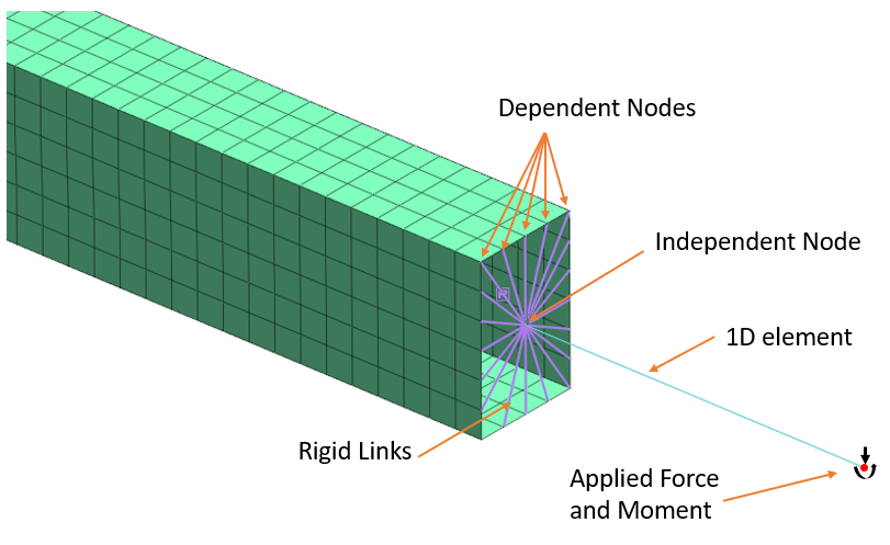
Rigid links constrain the relative motion between nodes. Here, the principal constraint node is the independent node and the principal constraint DOF is the independent DOF. The constrained node is the dependent node and the constrained DOF is the dependent DOF. Rigid links constrain the geometrically relative behavior of different nodes due to one node. Therefore, you can define one independent node with multiple connected dependent nodes. The coupled relationship between the independent and dependent nodes is as follows:
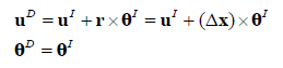
where uD, θD are the displacement and rotation of the dependent nodes, uI, θI are the displacement and rotation of the independent nodes, and δx is the vector from a dependent node to an independent node (xI - xD ).
The DOFs that are constrained by the independent nodes can be selected out of the 6 DOFs of the dependent nodes, and this can be used to generate the directional selective rigid links. The following example shows the constrained behavior in the x-y plane:
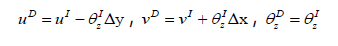
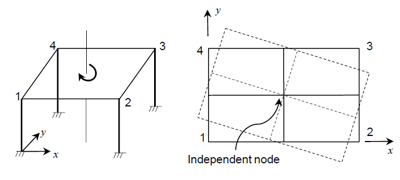 Figure 1. Example of rigid behavior in a plane.
- Why Use Links?
-
- Applying Concentrated Load to a Localized FEA Model
Structural engineers often use the 1D/grillage model to perform general analysis on civil structures. When they would like to investigate structural nuances to come up with a less conservative design, they need to use a detailed finite element method based on 2D plate/3D solid elements. However, due to the time cost and computational limit, they rarely model the entire structure using the detailed finite element method. Instead, they identify the localized structural zone based on the general analysis or engineering judgment and perform detailed analysis in those locations. The process is as follows:
- Perform general structural analysis using a 1D/grillage model.
- From the result above/based on engineering judgment, identify structural zones of interest.
- Model the localized structure explicitly and perform finite element analysis
In the example shown below, a bridge structure was modeled using midas Civil 1D elements. Based on the general analysis results, the structure connection shown in figure 2(a) is experiencing a high level of stress, however, the result does not tell us the specific stress distribution or any nonlinear behavior such as a potential fracture. Therefore, with a moderate level of modeling effort, a 2D plate element model is created in midas FEA NX, shown in figure 2(b), reflecting explicitly the localized box girder connection. Its inelastic strain plot is shown in figure- 2(b) and using this result engineers may be able to identify fracture initiation.
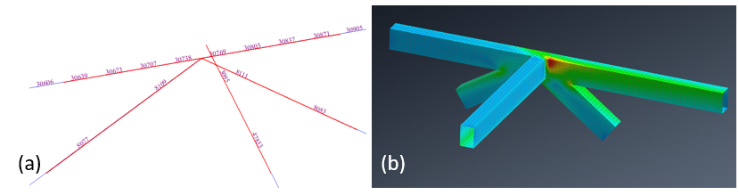
Figure 2. (a) 1D beam model in midas Civil showing the connection of structural concern. (b) 2D plate model in midas FEA NX showing the inelastic strain.
In the example above, force and moments are identified in figure 2 (a) at nodal points from the general analysis results (midas Civil) and applied as loads in the localized model. Rigid links are used to help distribute the load applied by constraining the motion between the independent and dependent nodes as shown in figure 3.

Figure 3. Rigid links are set up to connect the existing 1D element to the 2D plate element by constraining the nodal DOF on the 2D plate elements.
In figure 3, the independent node is on the 1D element where it transitions to the 2D elements. The rigid links are created by connecting the independent node with the dependent nodes, which are nodes on the edge of the 2D plate elements. The rigid links associate all 6 DOF of the dependent nodes to those of the independent nodes.
The second example shows how to add a detailed mesh section to a simple 1D beam element model. This example also shows using rigid links has an insignificant impact on the analysis results. The model shown in figure 4(a) is created in midas Civil 2022 v1.1 and was assigned a section property of AISC HP14x117 steel I girder. The beam is simply supported on 2 nodes, and gravity load is applied. The 1D beam model is then imported to midas FEA NX 2022 v1.1 using .mxt format, as shown in figure 4(b). Information regarding section property, material property, boundary conditions, and loads are also imported. The 1D elements in figure 4(b) are visualized with their section properties shown in orange, to not confuse them 2D plate elements.
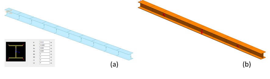
Figure 4. (a) I girder created in midas Civil subjected to gravity load using 1D beam elements. (b) 1D beam elements imported to midas FEA NX. With the 1D I girder section property visualized in orange.
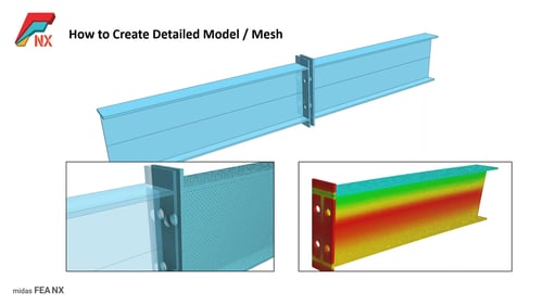
Two of the 1D elements in the center of the beam are deleted and 2D CAD geometries were created reflecting the section shape, as shown in figure 5(a). The newly added geometries were later meshed using 2D plate finite element, as shown in figure 5(b).
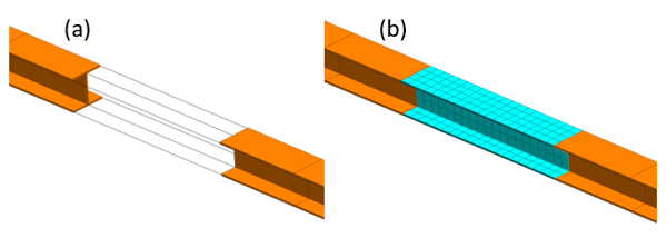
Figure 5. (a) 2D CAD geometries are created reflecting the I girder section (shown in transparent plates). (b) 2D shell mesh with an assigned thickness is created based on the 2D geometry.
To connect the 2D plate mesh with the remaining 1D beam elements, rigid links are used to constrain the independent nodes using the dependent nodes. As shown in figure 6, the independent node is on the 1D element and the dependent nodes are on the 2D elements.
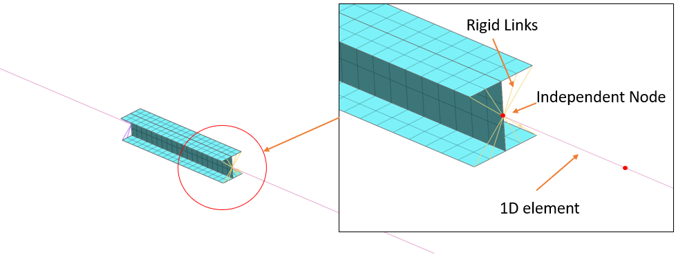
Figure 6. Connecting the 2D mesh to the 1D mesh using the rigid link to ensure loads are carried over.
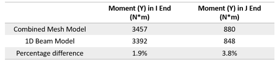
The results are used to compare with the original 1D model. Figure 7(a) shows the total displacement diagram of the combined mesh model, figure 7(b) shows the beam bending moment (Y) of the combined mesh model, and figure 7(c) shows the beam bending moment (Y) of the 1D beam model. The moment (Y) is measured at element 7:
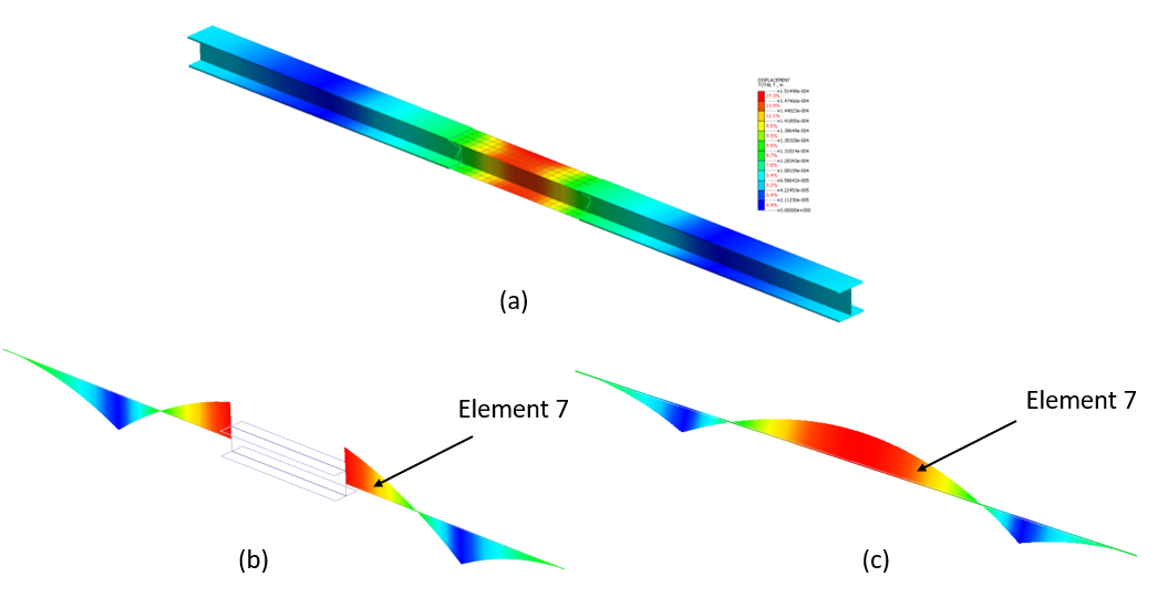
Figure 7. (a) Total displacement diagram of the combined mesh, 1D elements are visualized with section properties. (b) Beam bending moment in Y diagram for the combined mesh model. (c). Beam bending moment in Y diagram for the 1D mesh model.
Table 1. Comparison between the moment in Y at element 7 for both models.
https://www.midasoft.com/bridge-library/civil/products/midasfeanx

Related Articles
Structural connections are usually the weakest part of a steel structure; however, they are rarely the subject of structural analysis. To si...
In this Intro Session our MIDAS engineer explained about Midas FEA NX's capability in simulating structural connections such as contact, wel...
Structural connections are usually the weakest part of a steel structure; however, they are rarely the subject of structural analysis. To si...
In this Intro Session our MIDAS engineer explained about Midas FEA NX's capability in simulating structural connections such as contact, wel...
Structural connections are usually the weakest part of a steel structure; however, they are rarely the subject of structural analysis. To si...
123
Add a Comment