Expert Tip: Suspension Bridge Analysis Using Trigonometric Methods
Author: Seungwoo Lee, Ph.D., P.E., S.E.
Publish Date: 13 Jul, 2021
There are a couple of ways to analyze suspension bridges. As previously discussed (Uniqueness and Difficulties of Suspension Bridge Analysis), the deflection theory proposed by Melan and solved by Moisseiff is one of the first. The second one may be trigonometric methods proposed by Timoshenko (Theory of suspension bridges, Journal of the Franklin Institute, Volume 235, Issue 4, April 1943, Pages 327-349). In this article, a brief explanation of trigonometric methods and related excel, and the example bridge dimensions will be provided.
In the deflection theory, the girder deflection is assumed as some kinds of exponential function as below

The details of this formula will be discussed later. However, it should be mentioned that the term Hp is horizontal cable tension force due to the live load (or any additional loads other than dead loads) and shall be calculated by iteration.
Timoshenko assumed the girder deflection as a trigonometric function shown below,

This formula looks much simpler comparing those of deflection theory, but it requires some calculations to determine each ai.
Modern displacement methods assume the girder deflection as a cubical function shown below,

Timoshenko’s trigonometric methods give theoretically more exact solution than deflection theory and the convergency is faster, however, the required calculation itself is more voluminous compared to deflection theory. It was 1943 and computers might not be available to bridge engineers and this method was not easy to apply to real projects.
In the late 50s, three young (at least at that time) and brilliant engineers in Bethlehem steel developed a computer program using this method and has started to apply trigonometric methods to real projects (Kuntz, Avery, Durkee, “Suspension bridge truss analysis by electronic computer”, ASCE Conference on Electronic Computation, 1958).
They employed some minor simplifications and finally, Dr. Kawada in Japan improved full trigonometric methods and applied them to the mega suspension bridge projects in Japan. Dr. Kawada is the chairman of Kawada Industries, Inc., he is a respected suspension bridge designer, fabricator, and builder. One of his books was translated into English, History of the Modern Suspension Bridge: Solving the Dilemma between Economy and Stiffness.
The attached excel calculates maximum girder moments considering live load and temperature changes simultaneously in a non-linear way. Applicable only to three-span, two-hinged suspension bridges and can consider only distributed live loads, not concentrated live loads (In the long-span suspension bridges, the effects of concentrated loads are not controlling).
The detailed numerical theory itself is also quite interesting and will be discussed later.
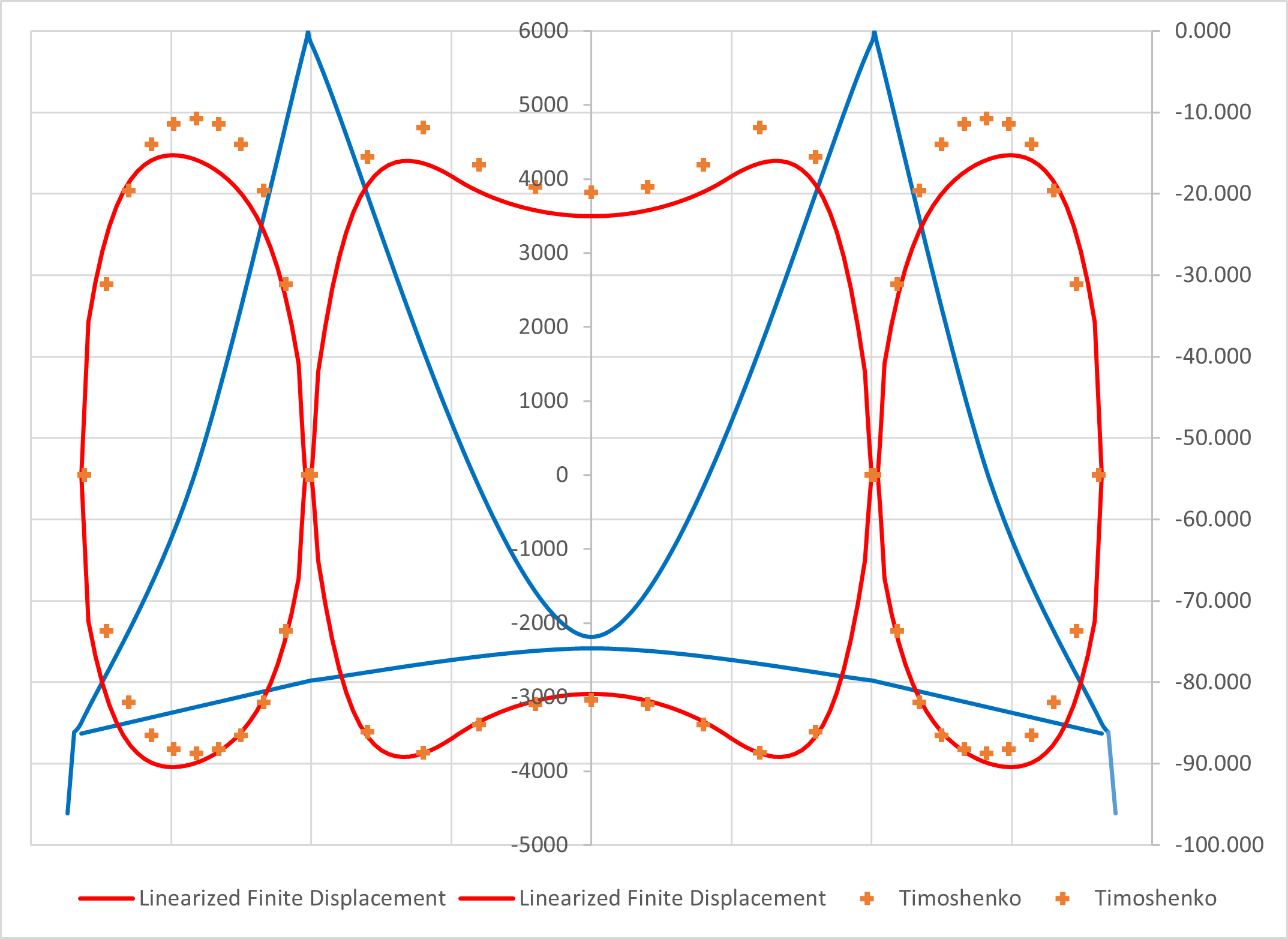
Figure 1. Girder moment comparison (Linearized Finite Displacement vs Trigonometric Method)
Figure 1 shows the girder moment comparison between the Linearized Finite Displacement and Trigonometric Method. The model is again the so-called A-Bridge and details are attached. The maximum difference is around 15% and the main reasons are
-
- In the trigonometric method, the effects of temperature changes are included, while not in the linearized finite displacement method.
-
- The assumed shape functions are different. (Trigonometric vs cubical).
From the author’s view, both methods give solutions with enough precision for practical application. The main shortage of trigonometric methods is, it is not easy to consider for wind/seismic loads. But, as can be seen from the excel worksheet, it is extremely easy to analyze for live loads with temperature.
This method is very useful at least in the preliminary design or design checks. With modern computers, the effectiveness of the trigonometric method shall be re-evaluated.
Add a Comment