Expert Tips: Strut-and-Tie Modeling for Pier Caps

Author: Daniel Baxter
Publish Date: 7 Mar, 2021
- What is Strut-and-Tie Analysis? What are "Struts" and "Ties" in Strut-and-Tie Analysis?
Strut-and-tie analysis visualizes the flow of forces through any type of concrete element in the form of internal truss. The tensile members of the internal truss are called "ties" and the compressive members of the internal truss are called "struts" in struct-and-tie analysis. The joints that are needed to join the two types of members together are called "nodes".
- When is Strut-and-Tie Analysis Needed?
Strut-and-tie analysis is suitable for regions of concrete structures that are in vicinity of the application of concentrated loads or are subjected to geometry changes. At those locations, often times the sectional analysis of the beam theory are not applicable. Most pier caps are subjected to concentrated loads from the superstructure, which are supported at the bearings. This results in disturbed regions on the pier cap where again, beam theory is not applicable. However, strut-and-tie analysis can perform design of the pier cap in scenario like this.
- How to Define the Strut-and-Tie Analysis Geometries?
To perform strut-and-tie analysis for a pier cap shown in figure 1(a), two types of model are created. The first one is a simple frame structure that is modeled using beam elements, as shown in figure 1(b). Superstructure can be included in this model. The second model is a natural strut-and-tie model of the pier cap that represents the internal truss using truss elements in order to model the internal forces.
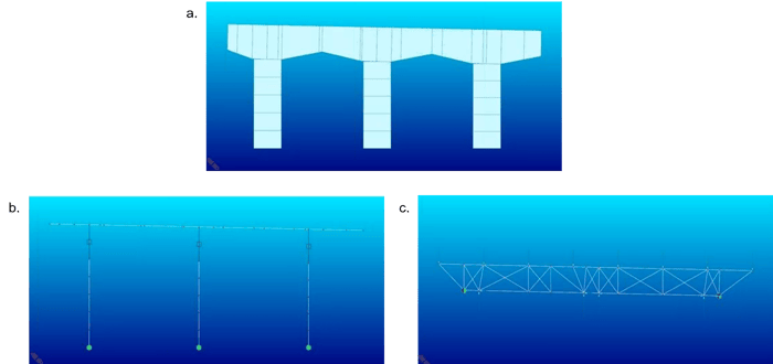
Figure 1. (a) Pier cap for strut-and-tie analysis. (b) Simple frame structure modeled using beam elements in midas Civil. (c) Strut-and-tie model representing the internal truss force modeled using midas Civil truss elements.
The first task to define the strut-and-tie analysis structure geometry is by defining the top and bottom ties. They will be placed at the centerlines of the top and bottom longitudinal steel. This is because we are going to use the force in our ties to directly design the reinforcement steel. For some cases where the pier cap might have longitudinal crack control reinforcement, but not all of these bars should be necessarily included as the tie members.
Nodes in the model are going to be placed at the intersection where the bearings of the girders are placed on the pier cap. We also need to place nodes in the model where the pier cap model intersects the columns, and the location of these nodes depends on if the columns are considered fixed support or pinned support to the pier cap. In the example shown in this article, they are considered fixed supports, therefore, the column nodes will be placed at the intersection of the quarter (1/4) points in the column and the steel tie elements at the pier cap bottom.
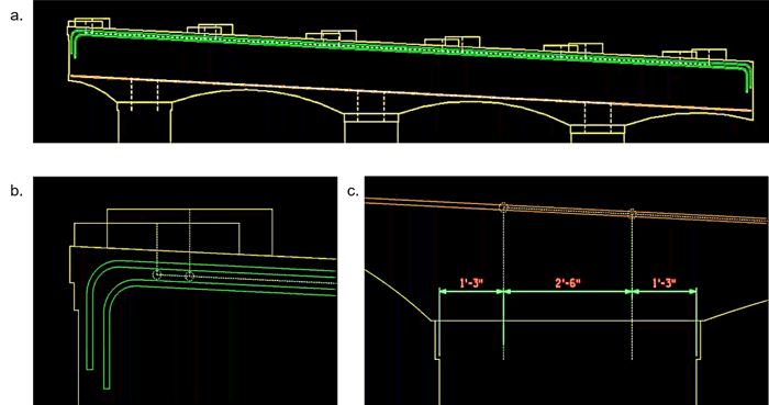
Figure 2. (a) Pier cap with top and bottom longitudinal steel reinforcement shown. (b) Girder loading locations, for this model the two girders for different spans are slightly offset. (c) Locations where pier cap intersects the column.
- How to Determine the Locations of the Vertical and Diagonal Members in the Strut-and-Tie Model?
Having determined the top and bottom ties and the locations of nodes that represents concentrated loads and supports, the preliminary strut-and-tie model gives a general idea of how the completed geometry would look like. However, to determine the location of additional nodes, vertical members, diagonal members, and additional members, the following steps and rules need to be followed.
-
- Follow the direct load path (draw structs from girder nodes to the nearest column nodes).
- Follow the 25° rule from AASHTO (no strut/tie should have less than 25° angle in between).
- Use overlapping X-diagonals between all vertical members.
The tensile force in the tie elements are used to design the reinforcing steel members. The X-diagonals are not expected to be in tension, but depending on the live load case placed on the superstructure, some may potentially go to tension. Therefore, X-diagonals are defined as compression-only elements in midas Civil.
- What are Examples of Good and Bad Strut-and-Tie Models?
Figure 3 shows examples of good and bad strut-and-tie models. As mentioned previously in figure 2(b), the girders are slightly offset at two spans, therefore the girder points are shown in figure 3(a). Instead of connecting the both girder points to the nearest column nodes that can result in load paths that are less than 25° from each other, shown in figure 3(a) and figure 3(b), the set up in figure 3(c) resolves this issue by using the average distance between both girder bearings. To comply with the 25° rule, the internal truss line in figure 3(d) can be resolved by adding an internal node shown in figure 3(e).
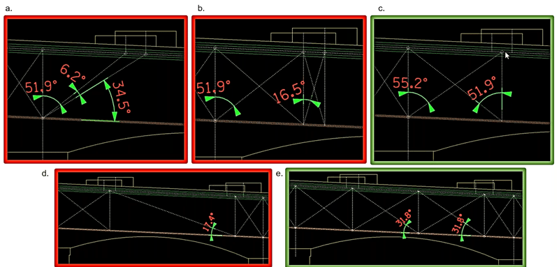
Figure 3. Examples of good (green) and bad (red) setups of internal nodes, vertical members and diagonal members.
The most efficient layout is the one having the least amount of vertical members in the internal truss, while complying to the 25° rule. Fewer vertical ties means more efficient use of material because the vertical force gets past the truss to each tie, and more ties means more force are needed to be designed for. Figure 4 shows an example of truss loading for two different truss designs. Eventually, half of the loading force P is taken to the supports, and despite the number of ties that are designed, they all subject to 1/2 P. Furthermore, less vertical ties means less reinforcing steel. This example shows that we can get rid of some of the verticals and replace the X-diagonals with direct diagonals and achieve the same effect.
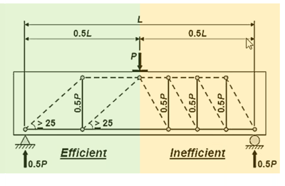 Figure 4. Truss loading of efficient and inefficient internal truss designs.
We might also need to do some iterations to determine the final locations of the nodes and diagonals. When iterating the nodal location, the nodes at the column locations and bearing locations should not change. However, some changes might be necessary especially the distance between the top and bottom chords. As mentioned previously, the chord elements would be at the centerline of the reinforcing group, and their positions can be adjusted by translating the nodes.
Once the geometry of the strut-and-tie model is determined, we begin construct the model using analysis software where the members are created using truss elements and compression-only elements for the diagonals. The boundary conditions applied to the model at the columns need to be consistent with the force and moment applied at the top of the structure. In the strut-and-tie model shown in figure 5, one pin and one roller is set as the boundary condition, and the rest of the forces were obtained from the frame model. They are applied to the strut-and-tie model as reaction force. The detailed process of how to obtain applied loads from the frame model would be covered in the next article.

Figure 5.Strut-and-tie model with boundary condition determined and applied loads obtained from the framed model analysis result.
To summarize the process of calculating and applying loads to the strut-and-tie model:
-
- Calculate the dead and live loads from superstructure.
- Apply superstructure bearing loads to frame model of pier cap and columns and obtain top of pier axial forces, moments, and shears.
- Apply obtained pier axial forces, moments, and shears to nodal reactions loads as boundary loads for the strut-and-tie model.
- Apply concurrent superstructure and reaction loads to the strut-and-tie model, and compute rating factors.
Editor: JC Sun
jsun@midasoft.com
Add a Comment