
Optimum crack angle θ From the previous example, we can catch that there are some possible crack angle ranges for the given εx and vu/f’c. N...

2 min read
Author: Seungwoo Lee, Ph.D., P.E., S.E.
Publish Date: 2 Jun, 2023
Findings and remarks
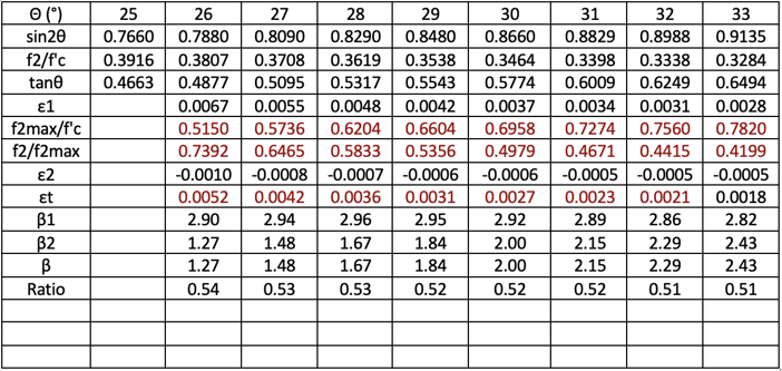
1. We can calculate the feasible crack angle ranges for each εx and vu/f’c combination. θ min corresponds to concrete crush and θ max corresponds to stirrup yielding.
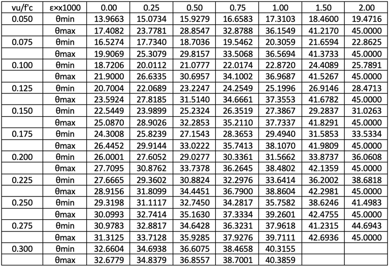
For εx=2/1000 condition, θ is 45° for stirrup yielding conditions, regardless of applied shear forces, because εt=2/1000.
This table is well-matched with what Rahal and Collins have provided. For large vu/f’c conditions, the θ min and θ max are very close to each other and even no solution exists εx>1.5/1000 conditions. From past experiences, εx=1.0/1000 and vu/f’c=0.25 are considered practical limits. Above these limits, a section increase may be recommended.
Θ min is the absolute minimum because the section would crush if θ < θ min. However, θ max is a kind of economical limit because if θ > θ max, just the stirrup would not yield. In some cases, the optimum θ may be larger than θ max and engineering judgments would be required.
2. The following figures show θ (°) values from various sources.
εx=0/1000, Optimum crack angle θ(°)
For εx=0/1000 conditions, θ max limit controls. In other words, because the strain is small, nominal amounts of stirrups are required. For vu/f’c<0.1 ranges, θ from Collins and Mitchell, AASHTO LRFD 2nd ed., Rahal and Collins are higher than θ max. “In these cases, the shear that needs to be resisted is relatively low, while the parameters that increase the concrete contribution, Vc, such as prestressing or high axial compression are significant (i.e., low values of εx). For these designs, the amount of transverse reinforcement required will typically be less than the specified minimum amount for members with transverse reinforcement.” (Rahal and Collins)
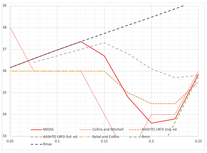
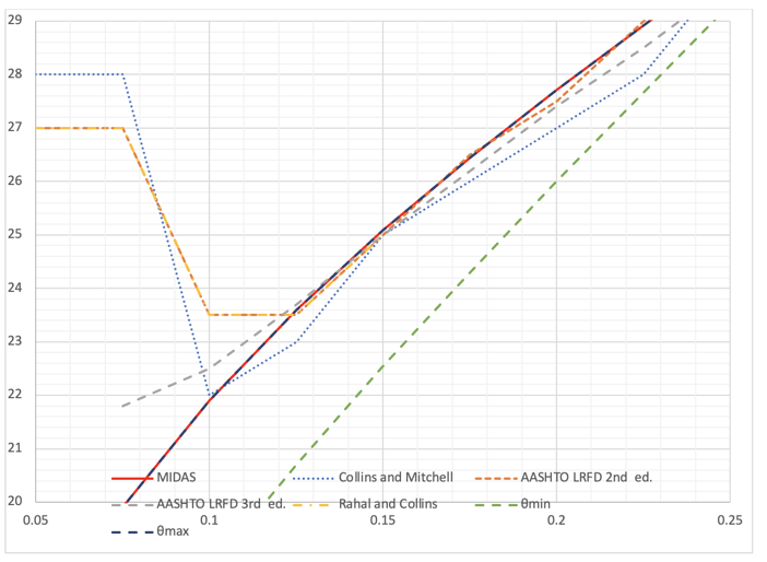
εx=1/1000, Optimum crack angle θ(°)
For εx=1/1000 conditions, θs from various sources show some differences. However, all graphs show θ values are moved from θ max to θ min with the increase of vu/f’c.
3. Following figures show β (psi) values from various sources.
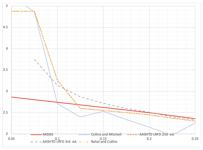
εx=0/1000, Optimum β (psi)
For the εx=0/1000 condition, β from all sources are close except vu/f’c<0.1 ranges. In this range, the shear force itself is small and engineers are less interested in this region. Again, the shear behavior of this region is close to without reinforcement case and will not be discussed in this article.
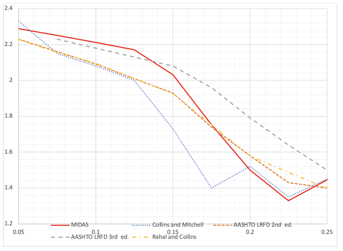
εx=1/1000, Optimum β (psi)
For the εx=1/1000 condition, β from all sources are close, but there are some differences. For vu/f’c=0.175, Collins and Mitchell show β=1.40, however, AASHTO LRFD 3rd ed. shows β=1.96. AASHTO LRFD 2nd ed., Rahal and Collins, and authors' results show around β=1.75. It may be interesting to find out where these differences are from but considering the uncertainty of concrete itself and all the assumptions introduced, these differences may be acceptable.
4. The modified compression field theory is a very powerful tool to understand the shear behavior of concrete. We can estimate the crack angle for given section forces, assumed stirrups, and longitudinal reinforcements. Of course, there are many uncertainties and assumptions within the theory, and it may be argued that this kind of lengthy calculation may not be justified. However, the reasonable crack angle θ is very valuable for our design and our fore-engineers had to wait a long time just to find out how to calculate θ.


Add a Comment