%20Calculate%20f1%20from%20vci.png?width=496&height=90&name=Step4)%20Calculate%20f1%20from%20vci.png)

%20Calculate%20%CE%B2.png?width=422&height=120&name=Step5)%20Calculate%20%CE%B2.png)
%20Calculate%20%CE%B52.png?width=434&height=85&name=Step6)%20Calculate%20%CE%B52.png)
%20Calculate%20%CE%B52%20further.png?width=591&height=284&name=Step6)%20Calculate%20%CE%B52%20further.png)
%20Calculation.png?width=712&height=106&name=Step7)%20Calculation.png)
.png?width=589&height=132&name=step%2010).png)

Concrete Shear Equation The concrete shear equation is

2 min read
Author: Seungwoo Lee, Ph.D., P.E., S.E.
Publish Date: 2 Jun, 2023
Optimum crack angle θ
From the previous example, we can catch that there are some possible crack angle ranges for the given εx and vu/f’c. Now our question is which values of θ and β are the optimums? The previous example shows that, without considering longitudinal reinforcements, mostly (not always) the lowest crack angle results in the least number of stirrups. However, with considering longitudinal reinforcements, the optimum crack angle increases. The methodology to find out the optimum crack angle is proposed by Rahal and Collins (Background to the general method of shear design in the 1994 CSA-A23.3 standard, Canadian Journal of Civil Engineering, February 2011).
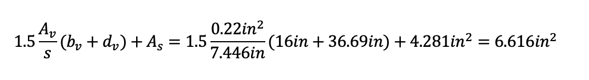
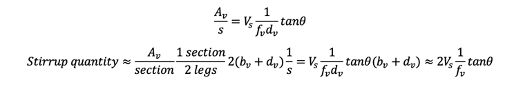
The total stirrup quantity per section is:
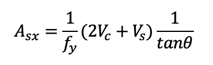
From the longitudinal reinforcement equation,
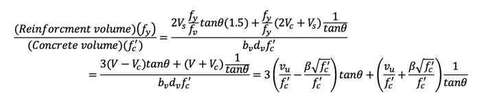
Increasing 50% of stirrup quantity by considering relative workability for bending and placing,
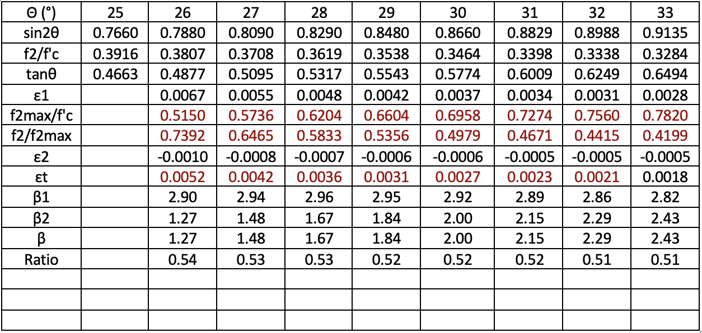
For εx=0.5/1000, vu/f’c=0.15 case, crack angle θ=32° corresponds to the minimum steel quantity case. AASHTO LRFD gives θ=32.1°, β=2.36, and close to what we got 2.29.
Detailed calculation
In the previous example, we calculated the maximum stirrup spacing with assumed longitudinal reinforcements. Now, with the help of computers, we can calculate the optimum stirrup spacing AND longitudinal reinforcements together. Detailed calculation steps are as follows.
Step 1) Assume ε1=0.003179
Step 2) Assume θ=37°
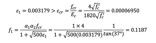
Step 3) Calculate f1 from fcr
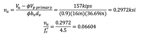
Step 4) Calculate f1 from vci
Assume fv=57.17 ksi, Av=0.22 in2, s=7.446 in.
Step 5) Calculate β
Step 6) Calculate ε2
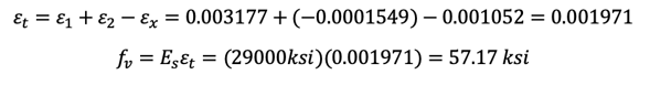
Step 7) Calculate εx
Assume As = 4.281 in2
Step 8) Calculate ε1
Repeat Steps 1) to 8)
Step 9) Calculate fv
Repeat Steps 4) to 9)
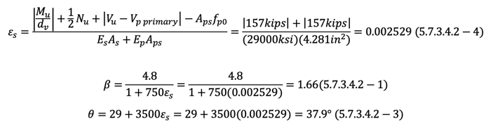
Step 10)
Repeat Steps 7) to 10)
Step 11)
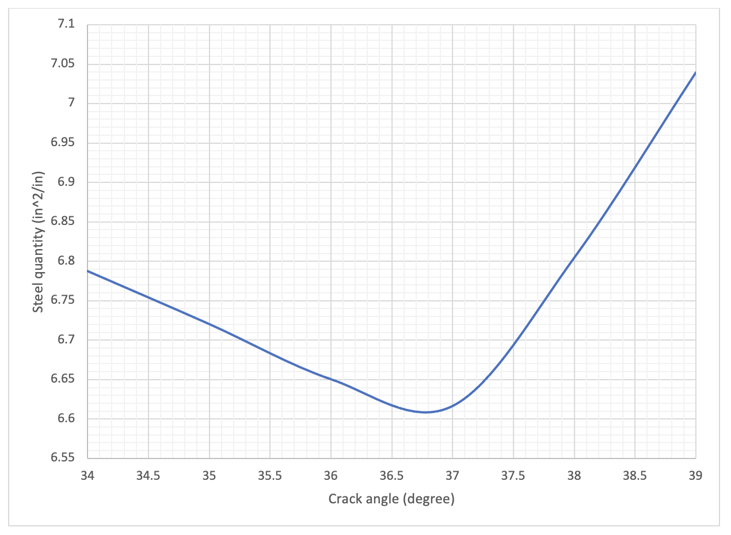
The same calculation can be performed for different crack angles as shown below.
From the figure, we can see that the optimum crack angle is around 36.75 degrees. With εx=1.052/1000, vu/f’c=0.06604, we got approximately θ=37°, β=2.35.
AASHTO LRFD gives θ=36.4°, β=2.23 for εx=1/1000, vu/f’c=0.075 case and these are very close to what we got with iteration.
Simplified methods
AASHTO 5.7.3.4.2 gives somewhat conservative results.
Conclusion
We can perform concrete shear design using modified compression field theory.
The modified compression field theory requires iterative calculations, but we have no problems with computers.
From the AASHTO LRFD appendix, we can find optimum crack angles and corresponding β values easily and these values are close to what we got from iterations.
AASHTO LRFD's main chapter shows a very simplified formula to calculate θ and β, and these are somewhat conservative values.


Add a Comment