
Concrete Shear Equation The concrete shear equation is

3 min read
Author: Seungwoo Lee, Ph.D., P.E., S.E.
Publish Date: 22 May, 2023
Longitudinal reinforcement
Believe it or not, longitudinal forces are caused by shear, and we do need to design/check for these longitudinal forces even under the pure shear condition. “Unfortunately, this concept was not included when the shear design procedures were originally developed. This omission can be a serious shortcoming”. (Design of highway bridges, An LRFD approach, 3rd ed. by Baker and Puckett, 2013)
This requirement is somewhat complex, but Collins and Mitchell explained it in a very elegant way as described below.
Before cracking condition,
From vertical equilibrium,
![]()
From stress equilibrium,
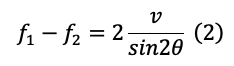
v is defined as
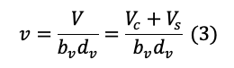
From eq (1),(2),(3)

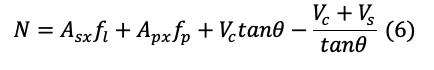
From horizontal equilibrium,
![]()
In eq (5), Asx and Apx are the “total” area of reinforcement and prestressing.
From eq (2),(4),(5)
AT after cracking condition,
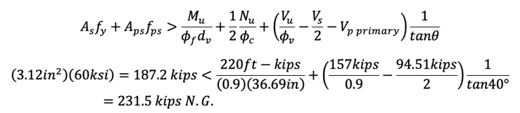
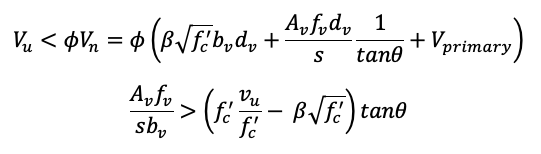
The following condition shall be satisfied.

The two vertical stress conditions at cracks and between cracks shall be statically equivalent.
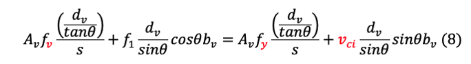
If the axial force on the member is zero, i.e., N=0, from eq (6),(7),(8)
Assuming the stirrups are yielding.
Considering only the reinforcement on the “tension side”, i.e., As=Asx/2, Aps=Apx/2,
Adding the effects from the moment and axial forces,
Eq (9) is what AASHTO LRFD gives as (5.7.3.5-1).
Practical Aspect
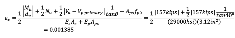
For the shear design, we need to estimate longitudinal strain εx. AASHTO LRFD allows us to assume εx as one-half of tensile strain εt since compression strain εc can be assumed negligible.
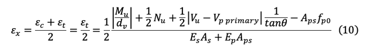
Eq (10) is what AASHTO LRFD gives as (B5.2-3).
If the value of εx from eq (10) is negative, the strain shall be taken as
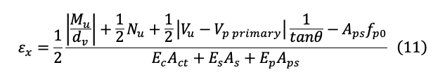
An act is an area of concrete on the “flexural tension side” of the member.
In eq (10),(11), Mu shall not be taken less than (Vu-Vp)dv.
Eq (10), and (11) need iterations since we do not know the crack angle θ at the beginning. AASHTO LRFD also allows assuming (1/2)(1/tanθ)=1.0, i.e., θ is constant at 26.57° to avoid iterations.
“Note that modified compression field theory provides an alternative regarding whether to increase longitudinal and/or transverse steel”. (Baker and Puckett)
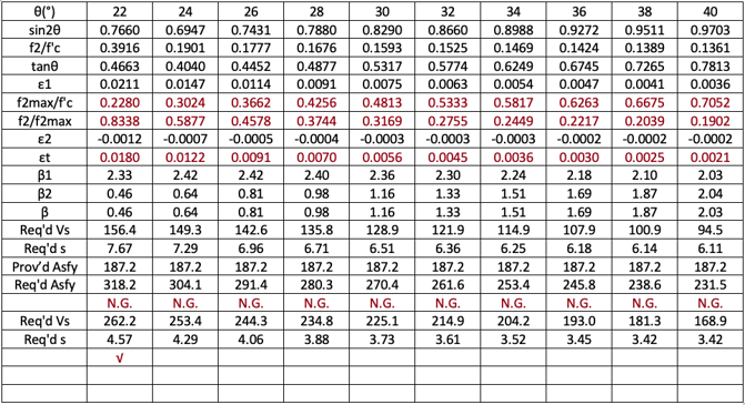
For given εx and vu/f’c, we can calculate some ranges of θs and corresponding βs. Now the problem is what value of θ should we use. Collins and Mitchell recommend “within the possible range of values of θ, the values given in the table will result in close to the minimum amount of shear reinforcement”.
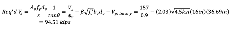
The required shear reinforcement is:
The Different Steps
If we assume tanθ is constant as AASHTO LRFD allows (when calculating εx), the minimum stirrup area corresponds to β max case. However, if we consider the variation of θ, we need more calculations.
Example (Ex14.3, Design of highway bridges, An LRFD approach, 3rd ed. by Baker and Puckett, 2013)
As always, the best way to understand a complex theory is to solve real problems.
f’c=4.5 ksi, bv=16 in., dv=36.69 in., As = 3.12 in2 (#11-2EA), Mu=220 ft-kips, Vu=157 kips.
Step 1)
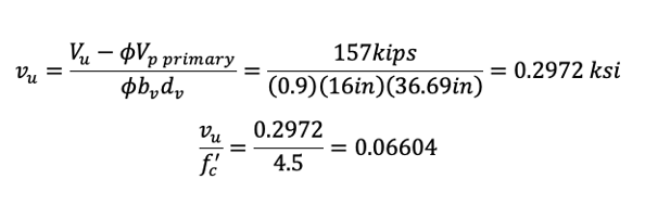
Step 2) Try θ=40°
Step 3)
Mu = 220 ft-kips < Vudv = (157 kips)(36.69 in) = 480.0 ft-kips
Step 4)
β can be calculated as β=2.03
(From AASHTO LRFD design table, θ=36.7°, β=2.18 for εx=0.001, vu/f’c=0.1).
Step 5)
With Av=0.22 in2 (#3-2EA), required maximum stirrup spacing is
For all valid ranges of θs, 22°~40°, we need to increase longitudinal reinforcements and/or reduce stirrup spacing.
These longitudinal reinforcement checks are not supplementary nor secondary but shall be checked and designed properly.
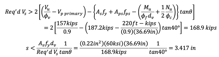
Step 7)
Try to reduce stirrup spacing with As = 3.12 in2 (#11-2EA)
S<3.42 in. is not practical.
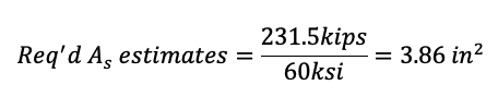
Step 8)
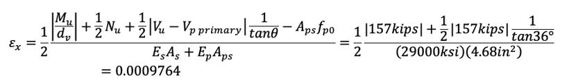
Try to increase longitudinal reinforcements. This calculation may look very simple, but we need to perform all calculations from the beginning because longitudinal strain εx varies with longitudinal reinforcements.
Try to increase longitudinal reinforcement with Av = 0.22 in2 (#3-2EA)
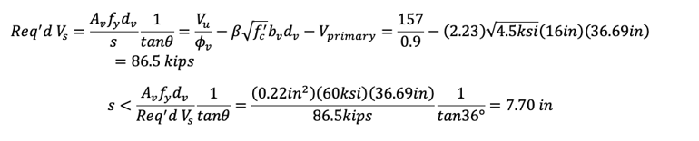
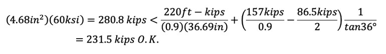
Try As = 4.68 in2 (#11-3EA)
Try θ=36°
β=2.23
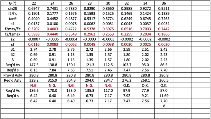
With the increase of longitudinal reinforcements, we can reduce shear reinforcements. This interesting fact has never been considered in the traditional approach and is one of the benefits of the modified compression field theory.
With the increased longitudinal reinforcements, the section works between the 32°~36° range of θs not considering any contribution from the shear stirrups. For the 22°~30° range, the section works with some contribution from the stirrups as shown in the last row.
Conclusion
With the modified compression field theory, we can consider the interactions between longitudinal reinforcements and stirrups. With the traditional approach, this is not possible.
We need some more calculations but there are no difficulties with computers.
The most economical stirrup spacing can be located somewhere between the lowest and highest crack angle ranges according to the longitudinal reinforcements,
We can consider moment-shear interactions easily with the modified compression field theory.


Add a Comment