In this MIDAS Intro Session, our MIDAS engineer introduced the underlying principles of buckling analysis, ways to interpret the modal analy...

3 min read
Author: Qi Zhang PhD, PE, PEng.
Publish Date: 14 Feb, 2023
So you have learned about column buckling under a point load applied at the end of the column, do you know if columns can buckle under their self-weight? Let’s explore it and run some analyses using midas Civil.
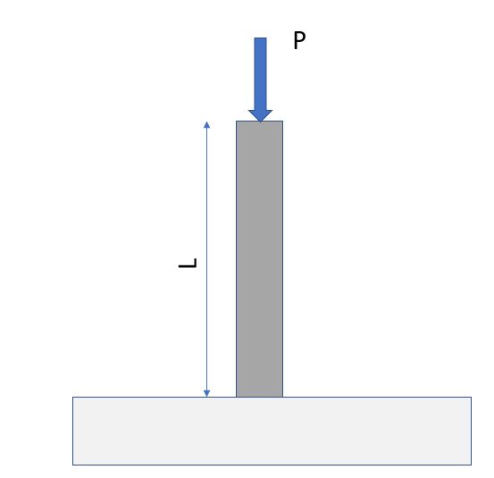
Before we do a self-weight buckling analysis, let’s review the Euler buckling equation when a point load is applied to a cantilever column. Assume a column with a height of L is fixed at the bottom and under a point load P at its free end, as shown in Figure 1. The differential equation that describes the relation of the column deflection and forces is shown in Equation 1. Solving Equation 1 and taking the lowest value as the solution of P would give Equation 2.
Figure 1. Cantilever column under a point load
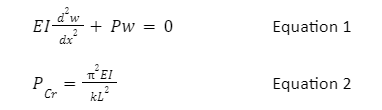
Where Pcr is the critical buckling load, E is Young's modulus of the material, I is the moment of inertia, L is the length of the column, and k is the column effective length factor. In the case of the cantilever column, k is 2. Let’s assume we are designing a concrete column with a diameter of 1 m and a height of 16 m. The properties needed to perform the buckling analysis are shown in Table 1.
|
Column Diameter |
D |
1 |
m |
|
Column Length |
L |
16 |
m |
|
Elastic Modulus |
E |
210000 |
MPa |
|
Effective length factor |
k |
2 |
- |
|
Moment of inertia |
I |
0.049 |
m4 |
Table 1. Column section and material properties
What is the critical buckling load for this column? Plugging all the numbers into Equation 2, we get:
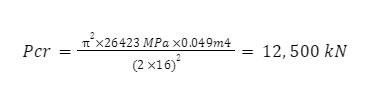
Now let’s run the analysis in midas Civil and compare the results. Setting up this analysis in midas Civil is to set up the cantilever column first and apply a vertical compression force at the top of the column. The magnitude of the force we apply does not matter; for instance, we can apply 1 kN or 15 kN or anything. However, for ease of getting the final buckling load, 1 kN is applied in this example. Once we set up the basic model with a point load, go to the toolbar, click Analysis – Buckling Analysis Control, ensure the Number of Modes is at least one, and select Consider Axial Force Only. Under the buckling Combination, select the Load Case where we would have defined the point load and click Add. That’s everything, just run the model now.
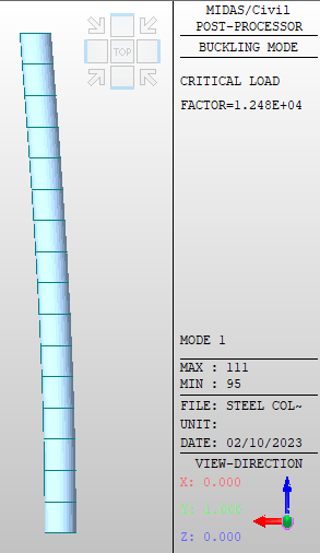
Once the model is run, click Results – Mode Shapes – Legend. We should see a factor on the right-hand side of the screen like the one in Figure 2. In this example, the factor is shown as 1.248E+4. To get the critical buckling load, we have to multiply this factor by the magnitude of the point load we applied, which is 1kN. Thus, the critical buckling load is 12,480 kN. In finite element analysis, the results can be sensitive to the number of elements we use to simulate this column. In this example, there are 16 elements, and the difference between the numerical result and the Euler buckling equation result is about 0.1%.
Figure 2. Column critical load factor under point load
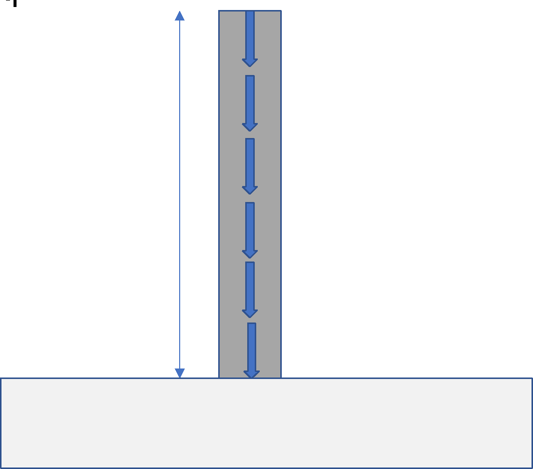
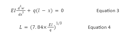
Now that we know how the software solves buckling load let’s look at if a column can buck under self-weight, as shown in Figure 3. Under gravity load, the column is under a uniform line load q caused by self-weight; it has a unit of kN per meter. It is a constant value of q because the column has a constant section throughout the height.
The equation describing the relation between load q and deflection becomes a bit more complicated, as shown in Equation 3. In this equation, we solve the length L instead of the loading q because q is a property determined by the material and the cross-section. Once we solve Equation 3 for the length L, we get Equation 4. Equation 4 expresses the column's maximum length before it buckles under self-weight q. Higher EI would allow a higher/longer column, and higher load q would reduce the length L.
Figure 3. Cantilever column under a self-weight
For the same concrete section and material we studied in Table 1, once we plug in the parameters to Equation 4, we get a column height of 83.1 m. This means that if the 1 m diameter concrete column is taller than 83.1m, it buckles under its self-weight. It is too tall to stand just because of its weight.
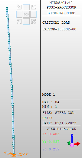
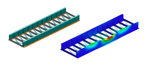
Let’s check this calculation using midas Civil. Define a column with a height of 83 m, and define a static load for Self Weight. In the Load Case of the self-weight, we should set the factor in the Z direction as -1. This tells the software that the gravity load is in the negative Z direction. All other steps for defining buckling analysis are the same as before. Hit F5 on the keyboard to run the analysis and have a look at the results. We should see a factor very close to 1.0, as shown in Figure 4, which means that this is the maximum column height we can build on earth! So how on earth do engineers build highrises taller than 83 m? By using multiple columns and other structural systems supporting each other! This way, the moment of inertia I of the entire system can be significantly increased. Columns and human beings are alike, “if you want to go fast, go alone if you want to go far, go together.”
Figure 4. Column critical load factor under self-weight

Add a Comment