.png?width=616&height=352&name=Displacement%20contour%20considering%20stiffness%20of%20slab%20(Finite%20Element%20Method).png)


When talking about refined analysis, most engineers might think of using it for complex bridges and bridges that are beyond the range of app...

5 min read
Author: MIDASoft
Publish Date: 7 Nov, 2023
|
Summary: The blog article discusses the differences between line girder analysis and the finite element approach. It also helps the readers understand the most recommended method using simple examples. Whether you're a seasoned engineer or just getting started, this article will enable you to choose the right approach for your projects. |
What is Line Girder Analysis?
Line girder analysis is a simplified method used in structural engineering to analyze and design bridge girders or beams without considering the stiffness of the elements.
Line girder analysis idealizes bridge girders as determinate structures and applies basic principles of structural mechanics and beam theory to assess their behavior under various loads. Even continuous beams will be analyzed span by span, assuming each span to be pinned or fixed supported, and the bending moments and shear forces along the beam can be back calculated.
Simple equations of equilibrium are used for the analysis of the girders: ∑Fx =0 ∑FY =0 ∑MY =0
Thus, this type of analysis is suitable for bridges with simple prismatic and relatively uniform configurations where the individual girders behave as independent structural elements, making this method unsuitable for bridges with multiple girders or flexible support conditions.
What is Finite Element Analysis?
The Finite Element Method (FEM) is a numerical technique used in engineering and computational science to solve analyze complex indeterminate structural systems like cable systems with varying stiffness.
The fundamental idea behind FEM is to dive the complex structural elements into smaller finite elements with simpler geometric shapes like triangles or quadrilaterals in 2D and tetrahedra or hexahedra in 3D and solve them separately, considering their stiffness. The finer the mesh, the more accurate the results will be.
[F] = [K] [∆]; [F] – Force [K] – Stiffness of the system [∆] - Deformation
Do Line Girder and Finite Element Analysis yield the same results?
Now comes the real question. Does Line Girder and Finite Element analysis give the same results?
Apart from deflection results, the bending moment and shear force outcome in a determinate structure like a simple supported beam doesn’t depend on the stiffness of the section. Thus, the analysis results of bending moment and shear force for determinate structures will be the same for both finite element and line girder analysis.
For indeterminate prismatic (Stiffness remaining the same throughout) structures, the results of bending moment and shear force will be the same for both finite element and line girder analysis. But, when there is a change in stiffness along the bridge, the results of both methods don’t match.
Let us discuss further on the matter using simple examples.
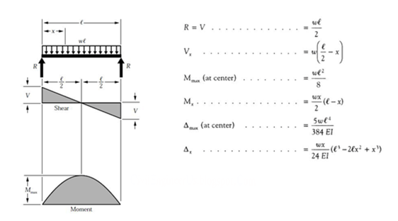
Case 1: Single span beam with constant stiffness
Let us take the case of 2 fixed beams with different stiffness.
Figure 1: Bending ç diagram for both beams
Figure 2: Shear force diagram for both beams
FEM, the stiffness parameters get cancelled out due to uniform cross section and generate results same as that of line girder analysis.
M fixed ends = wL2/ 12 = 83.33kNm
M mid-span = wL2/24 = 41.665kNm
V fixed ends = wL/ 2 = 50kN
V mid-span = 0
The deformations in the stiffer beam will be lesser than that on the slender beam and both methods can deliver the same deformation for the beams using the below formula.
∆ max = wL4/ 384 EI; EI being the stiffness parameter.
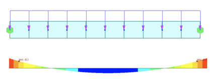
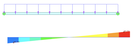
Case 2: Single span beam with varying stiffness
Let us compare a prismatic and non-prismatic beam, as shown below.
Now, for the finite element method, the beam will be divided into several parts, and the stiffness matrix of the system will be formed considering the stiffness of each element.
In the above figures, we can notice that the prismatic beam has a more symmetric BMD and SFD. But in the case of the non-prismatic beam (one on the right), more forces are accumulated towards left support compared to the right. This is because the stiffness of the elements on the left is more comparative and thus attracts more forces since [F] α [K].
In this case, again, the line girder analysis will give the exact bending moment and shear force values for the beams as that of the prismatic beam since this analysis method is independent of the stiffness of the elements.
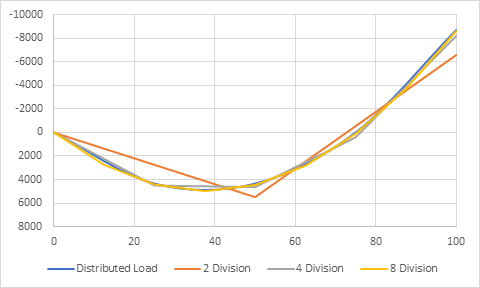
Load Distribution in Line Girder & Finite Element Analysis
Let’s take an example of a steel composite bridge with five girders. In a composite bridge, the steel girders and concrete deck work together to distribute loads. The load distribution depends on factors like the cross-sectional properties of the girders, the stiffness of the concrete slab, and the interaction between steel and concrete.
In the case of line girders, load distribution is not based on the stiffness of the members. The line girder analysis typically involves determining the distribution of loads along the length of the girders. Considering the effects of live loads, including axle loads and any other dynamic effects, you'll need to follow relevant design codes and standards to calculate the distribution of loads.
Load distribution analysis in a steel composite bridge using finite element analysis (FEA) is more detailed and comprehensive than line girder analysis. FEA allows for a more accurate and flexible simulation of the bridge's behavior under various loads. The loads will be distributed according to their position, the stiffness of the girders, and the boundary conditions assigned
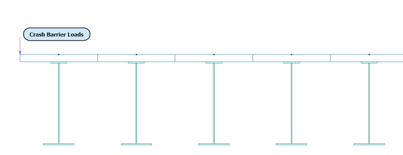
Figure 7: Steel Composite Bridge - Front view
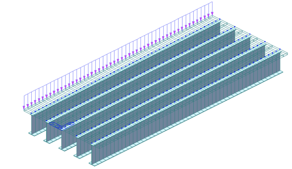
Figure 8: Steel Composite Bridge - 3D view
Let’s consider the effect of the crash barrier load assigned at one edge, as shown in the figure above.
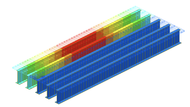
In the finite element method, due to the stiffness of the slab, the effect of the loads will be transferred
to other girders according to the stiffness of the sections. Meanwhile, in the line girder analysis, the
stiffness of the slab connecting the adjacent beams is neglected. Usually, the load will be distributed
to two or more girders following some assumptions since the actual load distribution is impossible
due to the absence of slab stiffness in the transverse direction. Thus, no load will be transferred to the
adjacent girders, and only the assigned beams will be affected by the crash barrier loads.
Figure 9:Displacement contour considering stiffness of slab (Finite Element Method)
Figure 10: Displacement contour without considering stiffness of slab: Crash barrier loads distributed to two adjacent girders (Line Girder Analysis)
You all must be wondering which one is the right approach. Keep reading.
The recommended approach– Line Girder Analysis or FEM
Two boys are lifting 100 lbs weight. One of them has more muscle in one hand compared to the other.
We all know that the first guy experiences the same load of 50 lbs in both his arms, irrespective of how strong he is.
But what about the second guy? Do you think both his arms will take the same load? No. The muscular arm should carry more weight compared to the slender arm to keep the dumbbells afloat.
This is applied to all the structures we see around us. The more the stiffness of an element, the more loads will be attracted to it. This is why more load is observed in the stiffer end of the non-prismatic fixed beam example mentioned previously. But in the same case, the moment and shear force deduced from line girder analysis is significantly less, and this underestimating of the loads can lead to the system's collapse.
Similarly, in the steel composite bridge, slab stiffness plays a significant role in load distribution. Ideally, the impact of the crash barrier will be felt by nearby girders, even though the effect will be minor. However, in the line girder method, transverse load distribution is neglected, which can lead to catastrophic outcomes, especially in the case of curved or skew bridges and bridges with varying sections.
Apart from straight single-span bridges with uniform cross-sections, the line girder method is deemed inaccurate.
Is Line Girder Analysis necessary in the 21st century?
The world is moving faster than ever before, and there is a growing need for more intricate and longer-span bridges and structures.
The decision ultimately hinges on the unique demands of your project. For simpler designs or initial assessments, Line Girder Analysis may suffice. However, in the 21st century, where innovation and intricate structures are the norm, FEM has emerged as the go-to solution for tackling the complex engineering challenges of our time.
With the right choice, you can build not just structures but also a safer and more sustainable future.
Add a Comment