Author: MIDASoft
Publish Date: 27 Nov, 2023
|
Summary: In this article you will get to know the key concepts and importance of RSI analysis for the railway bridge. If we don’t ensure proper design, monitoring & maintenance of bridges then what it can lead to we all have witnessed a lot of times. The purpose of this article is to develop awareness among engineers for the important advanced analysis that are required for the safety of all individuals around us. |
According to federal authorities on October 15, 2023, a train derailment in Colorado resulted from a broken rail, lead to the collapse of a bridge over an interstate highway. The incident caused the death of a truck driver and blocked the road for an extended period. The National Transportation Safety Board (NTSB) is currently investigating the cause of the broken rail and the failure of warning systems. The NTSB spokesperson clarified that there is no suspicion of sabotage in connection with the derailment.
The steel bridge, constructed in 1958, collapsed as 30 cars from a BNSF Railway train transporting coal derailed while crossing over Interstate 25. This also lead to closure of the main north-south highway in Colorado for several days. Subsequently, assessment of the extent of the damage was carried out by the crews involved.
Federal accident data highlights that broken rails and track issues are significant contributors to derailments. The National Transportation Safety Board (NTSB) has consistently advocated for increased installation of automatic monitoring systems on railways to detect track problems early and prevent accidents. This recommendation was reiterated in July after a fatal Amtrak derailment on BNSF-owned tracks in northern Montana two years prior.
Understanding the Bridge Collapse of I 25 - Past accidents
The pressure for safety improvements in the railroad industry has increased, particularly since a February derailment involving toxic chemicals prompted evacuations in Ohio and Pennsylvania. Over the past decade, there have been more than 12,400 train derailments in the U.S., averaging more than 1,200 annually, according to Federal Railroad Administration data.
An Associated Press review of derailment reports submitted by railroads to the Federal Railroad Administration revealed that at least 111 railroad accidents since 1976 were attributed to bridge failures or misalignments, averaging just over two accidents annually.
The recent incident follows a railroad bridge collapse in June along a Montana Rail Link route, leading to railcars with oil products plunging into the Yellowstone River. This resulted in the spillage of molten sulfur and up to 250 tons of hot asphalt.
Derailment as a major cause of the Bridge Collapse?
Broken rails are a leading cause of derailments. According to data from the Federal Railroad Administration, broken rails and welds are the most common reason for train derailments, making up more than 15 percent of derailment cases.
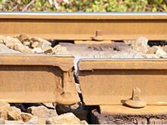
Fig1. Cracked rail which lead to rupture of whole section
Obviously, there must be proper monitoring system to keep on check with the condition of rails. But as a bridge engineer, it becomes the duty of the engineer to ensure that rail and railway bridge has been designed properly by keeping all the loads and interaction in account. Static loads are something which can be dealt easily by the engineer but the stresses & displacement in rail is something which is calculated based on rail structure interaction analysis. So, let’s understand this better.
What is Rail Structure Interaction?
Rail Structure Interaction (RSI) is a complex phenomenon that occurs between the rail and the structure when Continuous Welded Rail (CWR) is used on a railway bridge. Unlike conventional rails, CWRs are continuous rails, so each displacement that occurs on bridges and rails is influenced by each other due to train loading (vertical and longitudinal direction) and temperature changes. Due to the following effects, safety problems such as buckling or fracture may occur on the rail during use. Therefore, when using CWR, it is necessary to perform rail structure interaction to ensure stress and displacement are under limits.
When to Consider Rail Structure Interaction (RSI)?
According to UIC 774-3R clause 1.4, the RSI should consider cases that cause relative displacement of the track and deck.
The cases concerned are as follows:
In most cases, the first three effects are of major importance for bridge design
- The thermal expansion of the deck only, in the case of CWR, or the thermal expansion of the deck and of the rail,
whenever a rail expansion device is present - Horizontal braking and acceleration forces
- Rotation of the deck on its supports as a result of the deck bending under vertical traffic loads
- Deformation of the concrete structure due to creep and shrinkage
- Longitudinal displacement of the supports under the influence of the thermal gradient
- Deformation of the structure due to the vertical temperature gradient
The major importance that should be considered in bridge design are as follows:
- Thermal Expansion
Thermal action is the load case that has the greatest effect on the axial stress of the rail, but in the bridge section where the CWR is installed (central zone of CWR), there is no displacement of the rail due to thermal change, so it is not considered in the interaction.
The figure below shows that the expansion zone does expand and contract due to temperature changes. However, this does not happen in the central zone due to the ballast constraints.
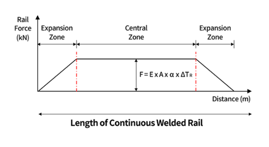
Fig2. Behavior of CWR under the effects of temperature changes
α : coefficient of thermal expansion
ΔTR : change in rail temperature relative to the reference or laying temperature
E : Young’s modulus for steel
A : combined cross-section of two rails
F : force in the track
The longitudinal displacement of the rail is fixed by sleepers, fasteners, and ballast, whereas the deck of the bridge is not fixed. Therefore, temperature changes occurring in the bridge causes relative displacement between the rail and the structure as shown in the figure below. Moreover, resistance of the track to longitudinal displacements is generated. This resistive force acts in the opposite direction of the rail and structure, but the magnitude of the force is the same.
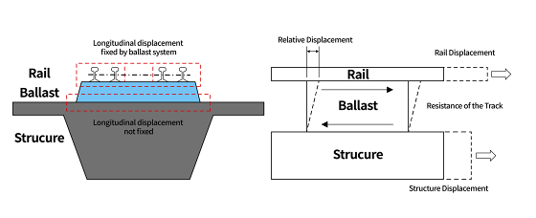
Fig4. Interaction on bridges under temperature loads
- Braking and Acceleration Forces
Similar to physical changes caused by thermal action, longitudinal resisting forces are also generated by the longitudinal displacement of the rail caused by braking and acceleration forces. The direction of the two forces with respect to the train’s traveling direction is opposite as shown in the figure below. If displacement occurs in the rail in the direction in which the load acts, additional displacements occur in the same direction through the interaction.
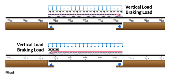
Fig5. Braking and acceleration forces action on the bridge
- Vertical Traffic Loads
Vertical train loads should be loaded at the most unfavorable position in accordance with what is being tested (ex. Stress occurring in rails or displacements occurring in bridges). Vertical train loads causes bending of the superstructure and causes end rotation between the upper edge of the deck end or between the upper end surface of the continuous deck as shown in the figure below.
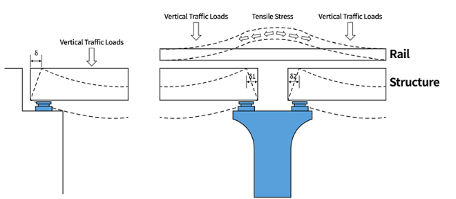
Fig6. Displacement due to deck bending
In addition, due to the rotation angle generated by bending, displacements are also transmitted to the rails, generating additional stresses. The conceptual diagram of the horizontal displacements due to bending of the superstructure are as follows.
.png?width=758&height=243&name=Effect%20of%20deck%20bending%20on%20the%20end%20sections%20(UIC%20774-3R).png)
Fig7. Effect of deck bending on the end sections (UIC 774-3R)

Add a Comment