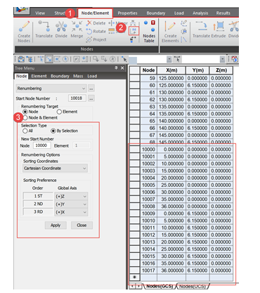
There are so many ways to help you save your time when you are working on your bridge project. One of the easy tips is renumbering of the no...

5 min read
Author: Seungwoo Lee, Ph.D., P.E., S.E.
Publish Date: 13 Jul, 2021

Believe it or not, once upon a time, there were no computers available for us, bridge engineers. At that time, we had to perform every calculation by hand using calculators or even slide-rules. It was quite dull and time-consuming. Now all we have cutting-edge computers, which is way better than those we used when we landed at the Moon. Everything looks nice, and life seems beautiful, doesn't it?
There are pros and cons, like every other thing in life. Computers don't have the capability to check the input and/or output. A long time ago, I had a chance to work with an engineer who has little experience. His duty was to calculate the deflection for a 30 ft span bridge. His estimation was more than 3 feet. I told him something wrong; however, he was quite confident with his estimation since he used a very well-known software. As we all expected, his input was not correct. Of course, there may be some bugs within the software itself; however, most of the wrong output comes from the incorrect input.
From that time, my main concern has been "how to minimize and/or avoid our input error?" My best answer is "to minimize the number of inputs itself." As the number of input decreases, the chances we input the wrong value also drops down.
For a steel composite girder, the shear design is rather simple compared to flexure design. It's still a little bit confusing because what we want is transverse stiffener spacing for given shear demands. However, the code formula provides the shear capacity for given transverse stiffener spacing. I found that we can perform shear design easily with a shear capacity diagram, and this diagram can be drawn only with a single input.
I used a typical three-span continuous, steel composite girder bridge, and from Design Example 1, Steel Bridge Design Handbook, FHWA-HIF-16-002-Vol. 20, 2015, as my example bridge.
Given Section Dimension
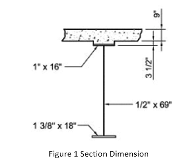
Web slenderness ratio D/tw is (69 in/0.5 in) = 138 and satisfies the web proportional limit 150 in Eq. (6.10.2.1.1-1).
The web height D = 69 in. is normally controlled by flexure design. The AASHTO/NSBA Steel Bridge Collaboration Guidelines for Design for Constructability recommend a minimum web thickness of 7/16 in., with a minimum thickness of 1/2 in. preferred and given section dimension satisfies this recommendation.
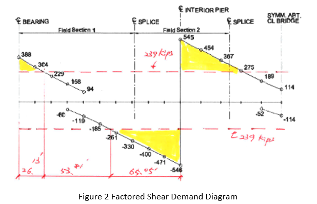
Shear Demand
The (factored) shear demand diagram is given as shown in Figure 2.
Shear Capacity
AASHTO LRFD Article 6.10.6.3 refers to the provisions of Article 6.10.9 to determine the nominal shear resistance at the strength limit state.
At the strength limit state, webs must satisfy the following:
Vu < φvVn Eq. (6.10.9.1.-1)
where:
Vu = factored shear in the web at the section under consideration
φv = resistance factor for shear = 1.0 (Article 6.5.4.2)
Vn = nominal shear resistance determined as specified in Articles 6.10.9.2 and 6.10.9.3 for unstiffened and stiffened webs, respectively
A flow chart for determining the shear resistance of I-sections is shown in Figure C6.10.9.1-1.
In the steel composite girders, shear design means to determine transverse stiffener spacing for given web sections. The required spacing of transverse stiffeners only for the left end parts will be determined in this example.
Nominal shear resistance of an unstiffened web
Determine the nominal shear resistance of an unstiffened web according to the provisions of Article 6.10.9.2. According to Article 6.10.9.2, the nominal shear resistance of an unstiffened web is limited to the shear yielding or shear buckling resistance, Vcr, determined as:
Vn = Vcr = CVp Eq. (6.10.9.2-1)
C is the ratio of the shear buckling resistance to the shear yield strength determined from Eq. 6.10.9.3.2-4, 6.10.9.3.2-5 or 6.10.9.3.2-6, as applicable, with the shear buckling coefficient, k, taken equal to 5.0.
Vp is the plastic shear force determined as follows:
Vp = 0.58FywDtw Eq. (6.10.9.2-2)
End Panel (Article 6.10.9.3.3)
According to Article 6.10.9.3.3, the nominal shear resistance of a web end panel is limited to the shear yielding or shear buckling resistance, Vcr, determined as:
Vn = Vcr = CVp Eq. (6.10.9.3.3-1)
C is the ratio of the shear buckling resistance to the shear yield strength from Eq. 6.10.9.3.2-4, 6.10.9.3.2-5 or 6.10.9.3.2-6, as applicable. First, compute the shear buckling coefficient, k. According to Article 6.10.9.3.3, the transverse stiffener spacing for end panels is not to exceed 1.5D.
Interior Panels (Article 6.10.9.3.2)
According to Article 6.10.9.1, the transverse stiffener spacing for interior panels without a longitudinal stiffener is not to exceed 3D. For interior panels of both nonhybrid and hybrid members with the section along the entire panel proportioned such that satisfy Eq. (6.10.9.3.2-1), the nominal shear resistance is to be taken as the sum of the shear yielding or shear buckling resistance and the post-buckling resistance due to tension-field action as Eq. (6.10.9.3.2-2).
Otherwise, the nominal shear resistance is to be taken as the shear resistance determined from Eq. (6.10.9.3.2-8). Previous specifications did not permit web panels of hybrid members to develop post-buckling resistance due to tension-field action. Also, note that previous provisions related to the effects of moment-shear interaction are no longer included in the specifications for reasons discussed in Article C6.10.9.3.2.
For the interior web panel under consideration:
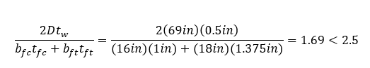
Therefore, the post-buckling resistance due to tension-field action can be considered in this example.
Shear Capacity Diagram
From the provisions of Article 6.10.9, it can be seen that shear capacity diagram (d0/D) vs (φvVn/Vp) is function of (E/Fyw) and (D/tw). However, in most cases (E/Fyw) is constant as (29000 ksi/50 ksi) = 580 and shear capacity diagram (d0/D) vs (φvVn/Vp) is only function of (D/tw). In this example, (D/tw) = 138 and shear capacity diagram (d0/D) vs (φvVn/Vp) can be drawn easily as shown in Figure 3.
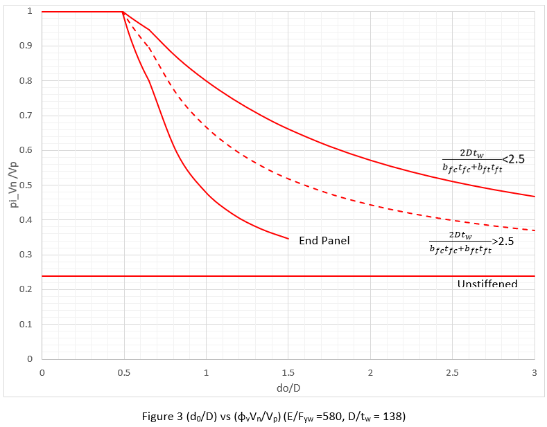
Figure 3 can be expanded into Figure 4 easily with the value of D = 69 in and/or tw = 1/2 in.
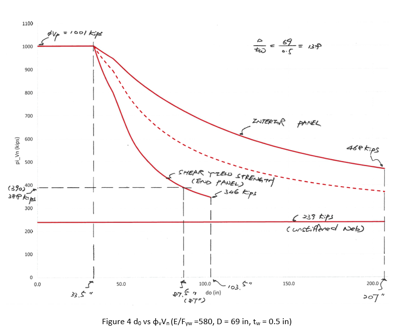
From Figure 4, we can see that:
- If Vu > 1001 kips (φvVp), we have to increase section dimensions, either web thickness or web height.
- If Vu < 239 kips (φvVn for unstiffened web), transverse stiffeners are not required.
- Transverse stiffener spacing closer than 33.5 in. does not increase shear strength and needs not be applied.
- If transverse stiffener is required, the maximum spacing is limited to either 1.5D = 103.5 in. = 8’-7 ½” (end panel) or 3D = 207 in. = 17’-3” (interior panel).
Shear Design
Step 1) The maximum factored shear demand is 546 kips (at pier 1). Vu = 546 kips is less than φvVp = 1001 kips and we need not increase given section dimension.
Step 2) Vu = 546 kips is larger than φvVn = 239 kips (for unstiffened web) and we need transverse stiffeners within 26.13 ft from abutment and within 65.05 ft from pier 1, at span 1.
Step 3) From Figure 4, it can be easily found that the required maximum transverse stiffener spacing at the abutment (Vu = 388 kips) is 87.5 in. Apply do = 87 in. = 7’-3” and the corresponding φVn = 390 kips (again can be found from the Figure 4).
Step 4) Vu at d0 = 87 in. from abutment is less than φVn = 468 kips (interior panel, with 3D = 207 in. spacing) by inspection. We need transverse stiffeners beyond 26.13 ft from abutment and the number of required transverse stiffener is (26.13 ft – 87 in.)/(207 in.) = 1.1 EA = 2 EA.
Step 5) The proposed transverse stiffener locations are 87 in. = 7’-3”, (87in.+201in.) = 294 in. = 24’-6”, and (294in.+201in.) = 495 in. = 41’-3”.
Step 5) Adjust transverse stiffener spacing as needed. In this example, intermediate cross-frame is assumed to be located 24 ft from abutment and this cross-frame connection plate can be served as a transverse stiffener. In this case, the 2nd transverse stiffener spacing is applied as (24’ – 87”) = 201 in. = 16’-9” from the 1st transverse stiffener.
Summary
As you can see, we can perform shear design for a steel composite girder with a shear capacity diagram which can be drawn with a single input, D/tw. Since there is only one input, the input mistake can be minimized. No other assumption is introduced, and the results are precisely matched with the codes.

|
Writer : Seungwoo Lee, Ph.D. Senior Supervising Engineer at WSP USA
Category : Bridge Date : 2020-03-02 |
Do you want to try the MIDAS Civil Software?
Don't you worry! We've got you a trial license.

Or get a license for $600/month!

Related Articles
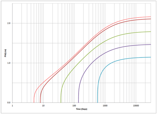
How to Perform Time-dependent Analysis? Mainly there are two ways to perform the time-dependent analysis. One is the time-step analysis and ...
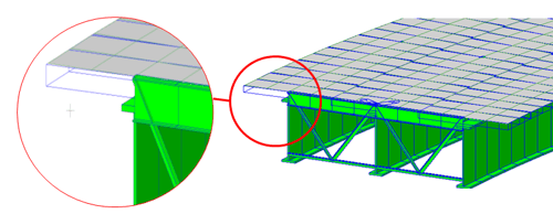
A complex bridge is one of the most common engineering projects nowadays. This category of structures includes movable, cable-stayed, segmen...
There are so many ways to help you save your time when you are working on your bridge project. One of the easy tips is renumbering of the no...
How to Perform Time-dependent Analysis? Mainly there are two ways to perform the time-dependent analysis. One is the time-step analysis and ...
A complex bridge is one of the most common engineering projects nowadays. This category of structures includes movable, cable-stayed, segmen...
123
Add a Comment