Believe it or not, once upon a time, there were no computers available for us, bridge engineers. At that time, we had to perform every calcu...

5 min read
Author: Seungwoo Lee, Ph.D., P.E., S.E.
Publish Date: 17 Jan, 2024
Economical design for steel composite bridge
|
Summary This article delves into the cost-effective design of steel composite bridges, with a focus on optimizing shop splice locations. Utilizing a method suggested by Korean engineers, the study calculates the optimum distance, considering the simplicity of the moment function. The exploration extends to continuous-span bridges, incorporating tables from Japanese engineers for optimization. Emphasizing the significance of reducing web thickness for economic design, the article advocates for using computers to determine optimal shop splice numbers and locations, showcasing potential steel savings. Cost comparisons underscore the benefits, concluding with a recommendation for a combined approach of past experiences, traditional aids, and computational analysis for efficient steel bridge designs. The forthcoming article will delve into finding the minimum sectional area for given moments. |
- Steel composite bridges are economical alternates where span lengths are around 200 ft range.
- Steel weights are closely related to the construction cost, and we can estimate the minimum construction cost by finding the minimum steel weights.
- To estimate the minimum steel weights, we must calculate the minimum steel area for arbitrarily selected sections and find out the optimum distance between shop splice locations.
- In this article, we will discuss how to find the optimum distance between shop splices.
- For a simple girder, traditionally we have assumed the required steel area is proportional to the moment and have tried to find the minimum moment area for each assumed number of shop splice locations.
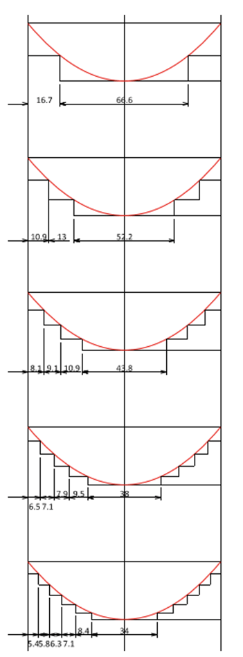
Fig. 1 Optimum shop splice locations for a simple girder
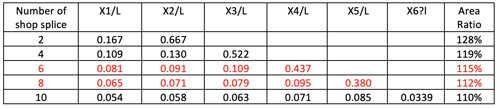
Table 1 Optimum shop splice locations for a simple girder
This method was suggested by Korean engineers as shown below (Korean Express Corporation, Highway Design Manual). This is a simple mathematical problem to find X1, X2,… which would produce the maximum dashed area.
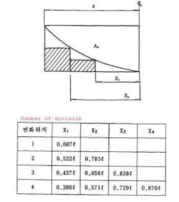
Fig. 2 Suggested shop splice locations for a single girder
6. For two splice locations, this calculation is as below.
Step1) Assume X1 = 0.667L
Step2) X2 = L/2-0.667L = 0.167L
Step3) M(X=0.667L) = M - M/(L/2)2 × (0.667L/2)2 = 0.556M
Step4) A/2 = (0.167L)(0.556M) + (0.667L/2)(M) = 0.426ML
Repeat Step1) to Step4) until A/2 is the minimum.
Step5) True A/2=(2/3)(L)(M)/2 = 0.333ML
Step6) (A/2)/(True (A/2))=128%
7. How can we tell if the calculated value of A/2 is the minimum?
We may need some kinds of optimal calculations or iteration. The moment function is a simple parabola, and the calculation is very simple, and we do not have any convergence problem. Also, we can apply manual or automatic iteration since the problem is quite simple.
8. How many divisions do we need to select?
It is up to engineers’ judgments. Many engineers believe that 6 or 8 divisions should be enough since adding more divisions would result in only 3% or 2% steel savings.
9. How about continuous spans?
For a simple span, it is very straightforward and clear to calculate the optimum distance between shop splices “based on given assumptions”, and this method has been well accepted by many engineers. However, the story shall be very different for continuous-span bridges.
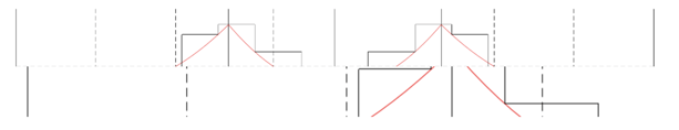
Fig. 3 Shop splice locations for a 3-span continuous girder
For a simple span bridge, we know that the maximum moment occurs at the span center and the moment diagram is close to a parabola, and we can reasonably assume the required steel section area is directly proportional to the moment diagram except at the end where the moment is zero, but the steel area cannot be.
For continuous span bridges, the moment diagram is dependent on several spans, span length ratio, moment ratio between positive and negative moments, locations of inflection points, etc. With many assumptions, like end spans are close to hinge-fix beam, center spans are close to fix-fix beam, and from past experiences, Japanese engineers have developed the following suggestions.
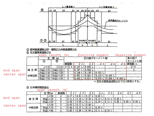
Fig. 4 Shop splice locations proposed by Japanese engineers
Table (1) was developed by Hanshin Express Company Limited and Fukuoka-Kitakyushu Expressway Public Corporation, table (2) was developed by Nagoya Expressway Public Corporation, and table (3) was developed by the Japan Bridge Association.
Many efforts and budgets were required to develop these tables and it is not easy to reproduce these tables just from mathematical calculations.
10. These tables are very elegant, easy to use, and very practical. How now we have 64-bit computes, and no reason not to calculate the optimum shop splice locations for each project.
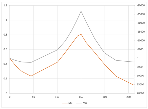
Fig. 5 Moments at strength limit state
Fig. 5 shows moment diagrams at the strength limit state for a 3-span continuous girder bridge, span length is 150’+223’+150’ = 523’.
%20vs%20required%20minimum%20steel%20area%20.png?width=528&height=384&name=Moment%20(ft-kips)%20vs%20required%20minimum%20steel%20area%20.png)
Fig. 6 Moment (ft-kips) vs required minimum steel area (in2)
From Fig. 2, we can see that the required steel area is not directly proportional to the corresponding moment diagram, especially at girder ends and inflection point locations. This is because we need minimum steels even though the moment is small or even zero.
Also, at the center of end spans, we may need additional steels from other than the strength limit state. In this example, the section at this location is controlled at the fatigue limit state.
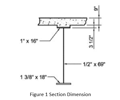
Fig. 7 Steel section composition
From Fig. 7, we can see that the web and bottom flange are dominant for steel weights. In other words, we must reduce web thickness as much as possible to achieve the economic design.
- To find out the optimum number of shop splices and the locations, we have to consider some practical limitations and suggestions.
- The distance between each shop splice cannot be too short. The recommendation is 3’.
- An additional shop splice can be justified only if we can save 100 to 200 kips of steel.
- Now we can find out the optimum number of shop splices and the locations with computers.
.png?width=528&height=210&name=Number%20of%20shop%20splices%20vs%20steel%20weight%20(per%20half%20bridge).png)
Table 2 Number of shop splices vs steel weight (per half bridge)
From Table 2, shop splice 5 or 6 ea should be responsible for this example bridge since an additional splice could save 2.0 to 1.0 kips of steel (1.0 to 0.5 kips per flange splice).
Usually, a savings in weight of between 0.8 to 1 kips should be realized to justify a flange butt splice.
From the Japanese Manual, 9 shop splices (per half bridge) are recommended and the corresponding steel weight of 115 kips is the same as 7 splices from this method. In other words, we can save a total of four, very expensive shop welding with this method which produces the same steel weights.
.png?width=528&height=388&name=Number%20of%20shop%20splices%20vs%20required%20steel%20volume%20(per%20half%20bridge).png)
Fig. 8 Number of shop splices vs required steel volume (per half bridge)
The theoretical minimum steel weight is 114 kips (per half bridge). Without any shop splice, the steel weight is 178 kips (per half bridge) and 60% heavier than the minimum. With 6 or 7 shop splices (per half bridge), the steel weight is around 2% heavier than the minimum.
.png?width=528&height=386&name=Optimum%20shop%20splice%20location%20for%206%20and%207%20shop%20splices%20(per%20half%20bridge).png)
Fig. 9 Optimum shop splice location for 6 and 7 shop splices (per half bridge)
Fig. 9 shows the optimum shop splice locations. Shop splice locations from the Japanese manual are also added for comparison.
We have no reason to apply the flange butt splices at the same location for the top and bottom flanges. With some additional calculation, we can find optimal butt splice locations both for top and bottom flanges as shown below.
.png?width=528&height=386&name=Optimum%20butt%20splice%20locations%20for%20top%20and%20bottom%20flanges%20(per%20half%20bridge).png)
Fig. 10 Optimum butt splice locations for top and bottom flanges (per half bridge)
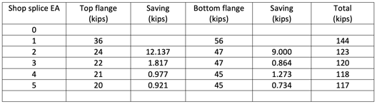
Table 3 Number of shop splices vs steel weight (per half bridge)
As can be expected, we can save some more steel if you add some more design efforts. With computers, these design efforts are nominal.
13. Is this all?
Not really. The resultant shop splice locations may not be exactly matched with the initially assumed splice locations and all above calculations shall be repeated.
With well-written codes (Steel bridge design manual, WSP USA), there is no difficulty in finding the minimum steel weights within three to five times iterations. Also, no unreasonable assumptions are introduced, and the results are very reliable.
The optimization technique is traditional and the source code is also available, for example, IMSL.
14. Closure
We must not underestimate past experiences or traditional design charts. However, it is also unreasonable not to check these aids with computers and try to save construction costs with refined analysis. Compared to the steel savings, the computational cost is nominal.
In the next article, we will discuss how to find the minimum sectional area for given moments.

Add a Comment