Overview The South Road Bridge is part of the $620 million Darlington Upgrade design/build project which provides for the improvement of app...
3 min read
Author: Zachary Taylor
Publish Date: 16 Feb, 2021
How to Model the Girder and Deck Connection in Composite Bridge?
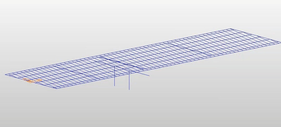
The way to simulate the connection between the girder and the deck will depend on how we construct the model. In the 2D all-frame composite bridge model shown in Figure 1, all the elements are connected in the grid within the same plane. Because it was modeled with the "all frame" model type in the midas Civil composite bridge wizard, it only consists of a 2-D grid frame composed of beam elements. In this scenario, the software considers the composite section as a lump section that incorporates both the girder section and the deck section. This means that the composite action is transformed into equivalent section properties in midas Civil.
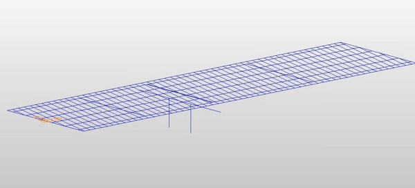
Figure 1. 2D "all frame" composite bridge model shown in midas Civil.
Midas Civil calculates the properties for the equivalent section using the elastic moduli of the steel (Es) and concrete (Ec) defined in the SSRC79 (Structural Stability Research Council, 1979, USA). The reinforcing bars are presumed to be included in the concrete section. In addition, the Ec value is decreased by 20% in accordance with the Eurocode 4.
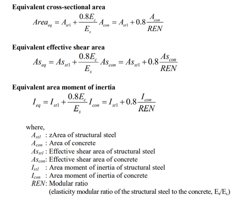
Figure 2. midas Civil analysis reference guide pg. 84 - stiffness of composite sections.
Therefore, to answer the question of how to model the girder-deck connection, the connection modeling is unnecessary if the composite bridge is modeled using the "all-frame" option in the composite bridge wizard. This is because the composite action is transformed into equivalent section properties.
Besides "all frame", we can also choose the modeling type to be "deck as plate, girder as frame" in the composite bridge wizard. The software will create plate elements separately for the deck. Then the beam elements representing the girders will be connected to the plate elements using the rigid connection. The rigid connection can be set up as shown in Figure 3, in which an additional node below the bottom of the girder node is defined. This node has a fixed boundary condition and is connected with the master node defined at the bottom of the girder using an elastic link to simulate the stiffness and thickness of the realistic bridge bearing. The nodes S1, S2, and S3 are slave nodes on the girder and the deck that would be dominated by the displacement of the master node. The article Types of Links in Midas Civil introduces types of links (rigid links, elastic links, etc.) in midas Civil and how to correctly model them in bridge structures. As far as construction stage analysis and time step method go, the rigid links explained above can be activated when the designed composite action happens in the sequence of the construction phasing.
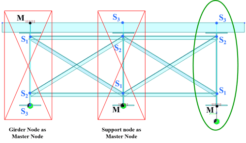
Figure 3. (Left) Incorrect boundary configuration where master node is the girder insertion at the top. (Middle) Incorrect boundary configuration where master node is the girder's bottom node. (Right) Correct boundary configuration where master node is an extra node defined a distance below the bottom of the girder, and the master node is connected to the girder bottom using an elastic link. Midas Bridge Library - Types of Links in Midas Civil (Luis J. Vila).
Are Plate Elements Suitable for Modeling Composite Bridges?
When we look at the two modeling types discussed above (all frame/deck as plate girder as a frame), the earlier one will be easier for post-processing and design code checking in the software. This is because the latter has two separate elements, the two will resist different forces making post-processing more challenging. Therefore, when doing prestressed girder design, I find the "all frame" model works better because all the force will be consolidated into one beam element. For post-tension girders, curve steel girders, etc., it might be useful to check things in plate elements. To help ease the post-processing in a model where beam and plate elements are combined, midas Civil offers the option called "section for resultant forces". When we use the "resultant force" option, the midas Civil wizard will automatically create resultant sections, which will help with post-processing by outputting a group of forces from plates and beams. Refer to midas Civil user manual > Section for Resultant Forces on defining resultant force sections to draw resultant force diagram.
How is Torsion on Curved Section Handled in Composite Bridge?
Torsions are calculated using the 3D FE method, however, there are extra efforts in midas Civil to capture the torsion effect with the 7th DOT option. In typical engineering practices, engineers are used to having six DOFs for modeling and analysis, however, additional advanced beam elements can include other DOFs to represent the warping of an open thin-walled cross-section. This option offered by midas Civil calculates the local warping effect on each of the element sections, therefore, it saves engineers time and effort by allowing them to model flanges as frames/beams instead of plates to obtain warping stress. The article Warping Stress in Midas explains and verifies how the warping effect is calculated in midas Civil 2D analysis.
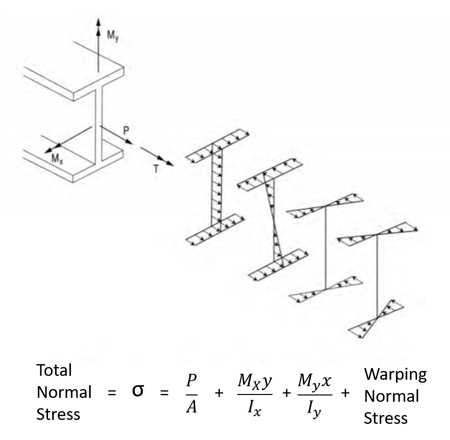 Figure 4. Illustration of the general I-girder normal stresses, which can occur in a curved or skewed I-shaped girder. (G13.1 Guidelines for STeel Girder Bridge Analysis, 2nd Ed.)
Why Do I See Negative Moments at the End of Supports of the Single Span Girder Bridges?
We do not expect to see a negative moment at the end of a simply supported beam in 2D analysis, although there might be some intricacies due to boundary conditions in 3D detailed analysis. There might be two possible reasons:
1. The supports are not at the centroid of the section. 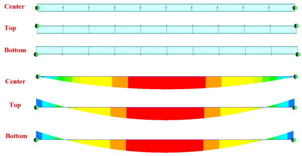
Figure 5. Bending moment diagrams of a beam whose supports are at the center/top/bottom of the section's centroid. Midas Bridge Library - Insertion Points, and Beam End Release (Luis J. Vila).
2. Beam end releases are not applied
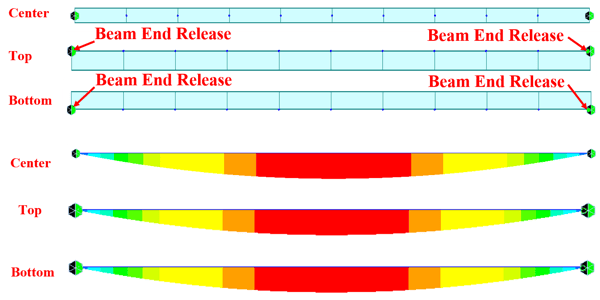
Figure 6. Bending moment diagrams of a beam whose ends are released and whose supports are at different positions relative to its sectional centroid. Midas Bridge Library - Insertion Points, and Beam End Release (Luis J. Vila).
Editor: JC Sun
jsun@midasoft.com

Add a Comment