Summary: In this article you will get to know the key concepts and importance of RSI analysis for the railway bridge. If we don’t ensure pro...

5 min read
Author: MIDASoft
Publish Date: 3 Oct, 2023
What is Rail Structure Interaction?
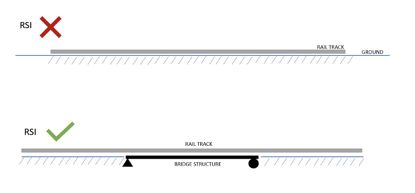
Rail structure interaction studies the interaction between railway tracks and concrete bridge structures. Differential stresses are generated in the rail and the deck of a railway bridge due to temperature, braking, traction, and the train's weight. Let's take two cases here. One interacts with rail and ground, and the other shows an interaction of rail and bridge. So, the area of interest is the second case, not the first one.
The need for RSI in the modern world
Rail structure interaction (RSI) remains crucial in the rail transportation era and with the recent development of high-speed trains globally, playing a vital role in estimating the impact of rail on the bridge and the optimum design of the bridge system for the safe passage of trains without disturbing the passenger's riding comfort. Most of the modern-day railways use CWR. Fish plate joints were used in which the length of each rail was around 20-40 m, but in the case of CWR, the length of rails is up to a few hundred meters. The fish plates allow certain deflections, releasing the stresses in the rails, while accumulation of stress occurs in CWR.
Let's take two scenarios: rails over an embankment and a bridge.
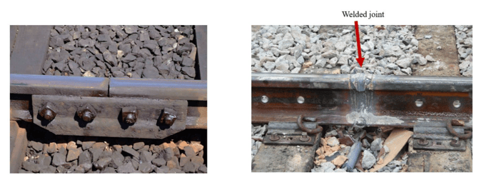
Figure 1:a) Fish Plate Joint b) Welded Rail Joint
Case 1: Rails on the ground
Let’s take a scenario and study the stresses in railway tracks when there is no bridge, and increase the temperature. We know that the ground won’t react to this change in temperature, but the railway track tends to expand. In the central zone, we can observe that there will not be any net force acting, and the stress profile is constant here.
- Stress = E x alpha x T
- Alpha - coefficient thermal expansion
- T - temperature rise
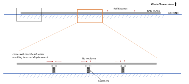
Figure 2: Central zone
But in the end zone, there is some net force which will result in some net displacement. This displacement will release the stresses and it tends to be zero.
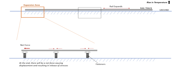
Figure 3: End zone (Expansion zone)
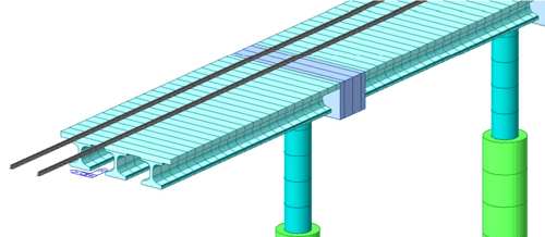
Case 2: Rails on bridge deck
Let us take the same case, but the bridge deck is connected monolithically with the track plinth, and the track plinth connects to the rail track using rail fasteners. But the rail fasters are not rigid and have a bilinear behavior. Due to this differential temperature, there will be thermal stresses in the deck and rail. These thermal stresses will tend to expand the deck and vice versa.
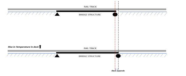
Figure 4: Differential stresses develop due to temperature
Code and guidelines for RSI
The guidelines and specifications are mentioned in the mother code of rail structure interaction
- UIC 774 3R.
Loads to be considered.
- Thermal Loads
- Braking and acceleration forces
- Vertical loads of the train
Effects that need to be considered while performing RSI.
- Additional stresses in Rail
Maximum Permissible Additional Compressive Stress: 72 MPa
Maximum Permissible Additional Tensile Stress: 92 MPa
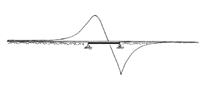
Figure 5: Example of a curve showing rail stresses due to temperature variation in bridge deck
- Absolute and relative displacement of the rails and deck
- Maximum Permissible displacement between rail and deck or embankment under braking and acceleration forces is 4 mm.
- The maximum absolute horizontal displacement of the deck is 5 mm.
- In the case of CWR on a ballasted track with an expansion device, the maximum permissible horizontal displacement of the deck under the same load is 30 mm.
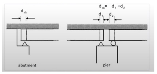
Figure 6: Limits to relative longitudinal displacement
- End rotation of the deck
Due to the vertical bending of the deck, the deck's end will rotate, and the permissible displacement between the top of the deck and the embankment between the two consecutive deck end due to vertical bending is 8 mm.

Figure 6: Limits to relative longitudinal displacement
- Bilinear behavior of the track
We have already discussed the bilinear behavior of fasteners earlier. Now, in the case of
tracks, the code has segregated them into ballast and ballastless tracks and has categorically
provided a curve defining the resistance - “k” for the longitudinal displacement of the rails.
The ballast has different stiffness in loaded and unloaded conditions, adding to the
nonlinearity of the analysis.
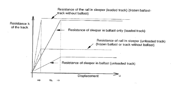
Figure 8: Resistance k of the track per unit length as a function of the longitudinal displacement u of the rails
Types of RSI Analysis
You might be wondering how to combine the results for temperature, braking, and vertical loads,
considering the nonlinearity of the bed. The superpositioning principle is invalid, making RSI analysis too complex. But don’t worry. UIC guidelines suggest two types of analysis to simplify our lives: The simplified Separate Analysis Method and the Complete Analysis Method. All the loads like thermal loading, braking, and traction loading are separately considered in a simplified separate analysis, whereas these loadings are concurrently considered in the case of complete analysis.
Simplified Separate Analysis
This is the simplest method for analyzing rail structure interaction. The thermal variation, braking/
acceleration forces, and vertical deflection are analyzed separately, and the results are combined,
assuming the principle of superposition. Since separate analysis is carried out for each load case, the assumption of zero initial stress and strain in the structure before train loading is considered.
Case 1
A model with temperature loads and resistance of ballast as per unloaded condition.
Case 2
A model with vertical train load, acceleration, and braking forces, which have different ballast resistance (loaded/ unloaded condition) depending on the presence of train loads.
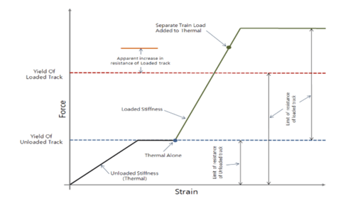
Figure 9: Longitudinal resistance of the ballast for separate analysis
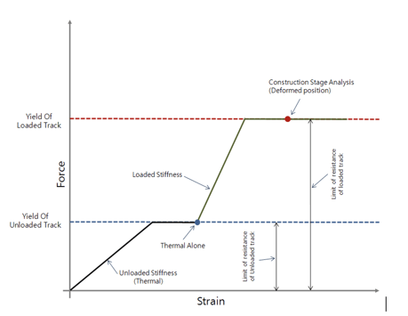
Complete Analysis Method
In Complete Analysis, the simultaneous effect of the thermal variation, braking/ acceleration force, and vertical deflection is considered, where the temperature load is applied first before the application of the vehicle load. The initial displacement due to temperature load is considered for the Analysis when the moving load is applied.
Figure 10: Longitudinal resistance of the ballast for a Complete Analysis
So, in short, we tend to overestimate the stresses in the case of simplified separate analysis as we linearly add the stresses in both the loadings, which we cannot do as the principle of superposition is not applicable for nonlinear (bilinear in this case) structures. But still, a simplified separate analysis is practiced in the industry as it is more conservative. The complete analysis would give more accurate and realistic results, but it depends on the designer which method to adopt.
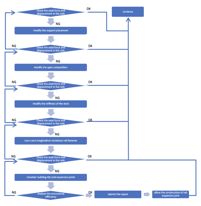
Steps in Rail Structure Interaction
Figure 11: Flowchart for RSI
What Makes Midas the Global Choice for RSI?
MIDAS has become the global choice for RSI analysis due to its robust capabilities, user-friendly interface, track record of success, and commitment to innovation.
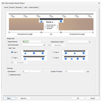
Midas Civil RSI wizard
Like the other Midas wizards, the RSI wizard is the most exciting feature most engineers working in the railway sector crave. Rail Track Analysis Model Wizard is provided to account for additional stresses and displacements due to an interaction between decks and rails.
The wizard facilitates Separate and Complete analysis considering the nonlinear properties of the ballast. Analysis is performed to find the location of the maximum additional stress by moving the train forward. When the train is moved forward, models that reflect the changes in boundary conditions are automatically created. Detailed reports are generated.
Figure 12: Rail Track Analysis Model Wizard
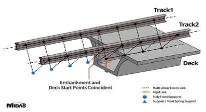
Figure 13: Boundary conditions simulating loaded and unloaded stiffness of the ballast.
Aside from the wizards, analysis results are periodically validated and widely trusted. According to UIC 774-3 (1.7), computer programs for track-bridge interaction analysis must undergo validation for test cases outlined in Appendix D. Validation is achieved when errors for both individual and overall effects are below 10%. UIC 774-3 permits a higher 20% tolerance if it leads to safer results.
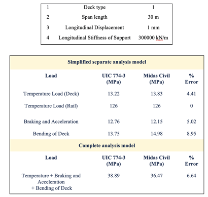
As a test case, our engineers have validated the RSI analysis results for the following bridge configuration.
Click here for more info.
Table 1: The bridge configuration is as follows as per UIC 774-3 A1-3 test case
From the above results, we can conclude that the results obtained from Midas Civil match well with the UIC 774-3 results and have an error within the permissible limit of the code, which is 10%.
What’s next?
As the rail industry evolves, so will the challenges and opportunities related to RSI. Engineers and researchers will continue to push boundaries, developing innovative solutions that enhance rail transportation in our ever-connected world.
As we journey into the future of rail engineering, MIDAS will continue to evolve, adapting to new challenges and innovations in the industry.
Its role in shaping the world of rail structure interaction remains pivotal, promising a safer, more efficient, and sustainable future for rail transportation.
The upcoming blog will discuss the Rail Structure Interaction in curved railway bridges. Stay tuned.
Related Articles

Check out how our MIDAS Users apply our software on their RSI projects by downloading the PDF below. You will get a breakdown of the modelin...
Summary: In this article you will get to know the key concepts and importance of RSI analysis for the railway bridge. If we don’t ensure pro...
Check out how our MIDAS Users apply our software on their RSI projects by downloading the PDF below. You will get a breakdown of the modelin...
Summary: In this article you will get to know the key concepts and importance of RSI analysis for the railway bridge. If we don’t ensure pro...
Check out how our MIDAS Users apply our software on their RSI projects by downloading the PDF below. You will get a breakdown of the modelin...
123
Add a Comment