
What is Application Programming Interface (API)? The first thought that will come into your mind is exactly what is this API? and why a civi...
3 min read
Author: MIDASoft
Publish Date: 8 May, 2023
The different types of finite element models one can generate
2D, 3D, and 4D finite element models are employed to analyze structures. Since culverts are relatively small and don't involve many construction stages, time, the 4th dimension, is neglected in most cases.
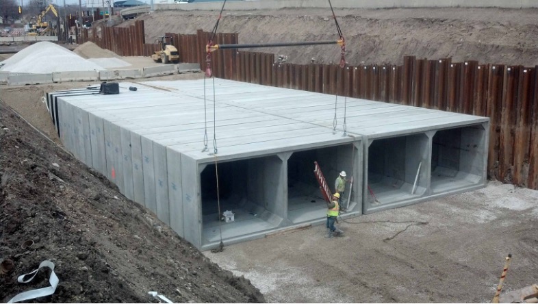
So, most might wonder what 2D and 3D analyses are. Don't worry; click here to learn more about them. Basically, it's just about the space. 2D analysis can be performed if all the members, boundary conditions, and loads acting on the structure can be idealized in a single plane. Consider an example of a simple box culvert, as shown in Figure 1. Even though the structure is three-dimensional, we can analyze the system in the 2D plane because of the prismatic cross-section. The significant forces, such as earth pressure, moving load, and dead load, can be assumed to act horizontally and vertically in a single plane.
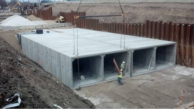
Figure 1: Simple box culvert
Now take an example of a simple tall building in a seismic zone. Significant forces such as earthquakes, wind, and dead loads cannot be idealized in a single plane. In these circumstances, designers usually go for a 3D analysis of the system.
Which finite element model is the best?
As mentioned above, the choice of analysis depends on the space but also on the discretion of the engineer. One must have a clear idea about the results they want from the model. For example, while modeling a bridge, a line element works fine rather than plate elements since bending moment and shear are the governing results. Likewise, plate elements are used to get the in-plane stiffness instead of beam elements with a large width while modeling the deck.
Usually, 2D analysis is carried out when the structure is regular, for example, a box culvert. Meanwhile, when the form is skewed or has a curvature, 3D analysis is used.
Beam elements are used to model 2D culverts. The structure's walls and the deck are conceptualized as beam elements that enable the designers to tap the stresses and forces coming onto them due to the lateral earth pressure and vertical loads due to traffic and dead load flexure being the keen design factor. The deformed shape, along with the displacement contours, can also be extracted.
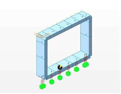
Figure 2: 2D approach - Simple box culvert comprising of beam elements
Plate elements and beam elements simulate the walls and deck of 3D culverts. It enables us to accommodate irregular geometry, out-of-plane boundary conditions, and forces in our model.
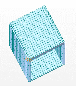
Figure 3: 3D approach - Skew culverts comprising of plate elements
Analysis and design of culverts
2D culverts are analyzed as beams with unit widths. Since each of the walls, deck, and foundation are represented by beams, bending moments and shear forces due to the external forces are extracted for 1 m length of culverts in the transverse direction. The components are designed as beam elements according to the respective national codes.
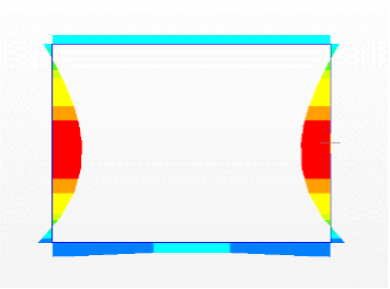
Figure 4: Beam moment about Global Y due to earth pressure in 2 D approach
In the 3D analysis approach, the actual plate action of the structure due to external loads can be obtained. Unlike 2D analysis, the total forces acting, and the real-life deformed shape of the system can be extracted.
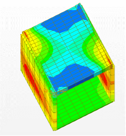
Figure 5: Plate moment, Mxy due to earth pressure in 3D approach
Engineers can also consider the Wood-Armer stresses for the design in this approach. Wood-Armer stresses consider the twisting moments due to external loading in the design of slabs, aiming to prevent yielding in all directions by the normal moment yield criterion.
At any point in a slab, due to the moments in X, Y, and XY directions, in-plane torsional moments are developed, which should not exceed the ultimate moment of resistance in that direction. The maximum normal resisting moment is typically provided by ultimate resisting moments Mux and Muα related to the reinforcement in the x- and α directions. Mx, My, and Mxy are bending and twisting moments, usually obtained from a finite element or grillage analysis program. The sign convention needs to be altered if it differs from the above. α is the angle of the transverse steel, measured clockwise, from the Mx axis.
M*x = Moment to be resisted by reinforcement in the x direction
M* α = Moment to be resisted by reinforcement in the α direction
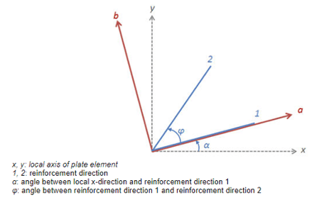
Figure 6: Wood Armer stress calculation
Midas to the rescue
By now, we know that 3D analysis is time-consuming and complex, even though it is inevitable in analyzing intricate structural systems. There arise times when correcting existing 3D models, like deletion and regeneration of meshes, can be stressful if we miss out on something. Thus, most prefer 2D analysis over 3D, even though the latter is more precise.
Don’t worry. Midas Civil has inbuilt wizards that enable the users to model and generate 2D and 3D structures in the nick of time, along with boundary conditions and loads with provisions for skewness and soil structure interaction. Visit my previous blog to experience the wide variety of culverts that can be modeled using Midas (All You Need to Know About Culverts (midasbridge.com)).
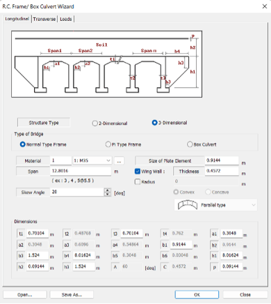
Figure 7: Culvert Wizard feature in Midas
Reference
[1] Wood, R.H., “The Reinforcement of Slabs in Accordance with a Pre-Determined Field of Moments,” Concrete, V. 2, No. 2, 1968, pp. 69-76.

Add a Comment