
Author: Daniel Baxter
Publish Date: 1 Dec, 2020
In the design project to replace the old Fulton Road arch bridge in Cleveland, OH, Michael Baker Intl engineer Daniel Baxter and his team has designed a 1,568-foot-long replacement structure for the original arch bridge, which retains the original design of six 210-foot-long concrete deck arch spans. For the replacement bridge structure, a precast, post-tensioned concrete arch bridge design was selected. You may be asking yourself, why post-tensioning the arch bridge? Arches usually provide sufficient stabilities to structures and it is not usual for bridge designers to post-tension such structures. In this tip, Daniel Baxter talks about why his team has decided to post-tension the arch bridge and how they have utilized construction stage analysis to design the post-tension process.
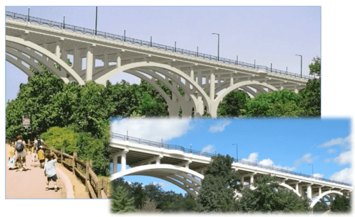
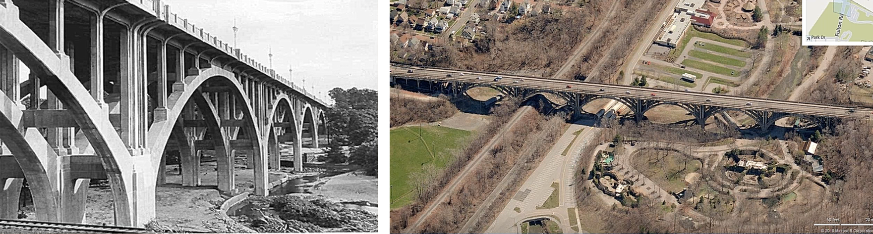 Left: The original Fulton Street Bridge structure (now demolished). Right: Aerial view of the new Fulton Street Bridge.
The image blow shows the arch layout of one of the six arch spans, where there are four arch ribs throughout the lateral span. Four spandrel columns also sit on top of the arch ribs supporting the superstructure.
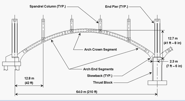
Arch layout
In this case, the combination of the arch sitting on the piers which have a fair amount of flexibility and the spandrel columns being widely spaced (42 ft) introduces concentrated load on the 4 locations on the arch. These factors also create more bending on the arch than the traditional arch. Using bending moment diagram of the arch under dead load and live load, shown below, we can understand why we are seeing such large bending moment during the design process. We started with the very basic arch on rigid support (red), then we compare the bending moment curve of the arch with actual support which have rigid support (blue) and with flexibilities (green). Eventually, we obtained the bending moment curve (gold) of the bridge structure with influence of the piers with flexibility of their foundations, and also adding in the effect of construction sequence analysis produced in midas Civil software.
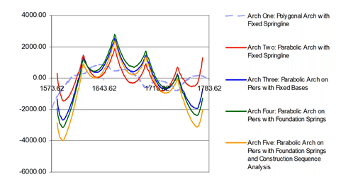
Bending moment diagram of the single arch under dead load and live load
When we look at the stresses in the arch, shown below, we can observe few regions where the stress exceeds the AASHTO limits, particularly near the end segments where the end segments meets the pier bases. Depending on the live load, the stress level at the intermediate spandrel columns also exceed the stress limits. This design has fewer spandrel columns than traditional arches, therefore, more stress is introduced and we have chosen post-tension in order to meet the stress limits requirement.
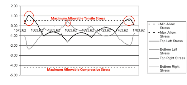
Stress distribution on the top and bottom surfaces of the arch span
However, more challenges came up with the post-tensioning design. These arches have fixes stands to them, and if engineers try to use eccentric post tensioning to counteract bending moments, those fixed stands will experience significant restraints. This would result in secondary moment that will cancel out any beneficial primary prestress moment obtained from eccentric post-tensioning. Therefore, construction stage analysis is used that introduces eccentric post-tensioning was introduces during the structural configuration that does not have the full rigidity of the completed arch. Because it does not have the full rigidity, the segment is able to deform due to the eccentric pre-stress force, and thus introducing beneficial primary pre-stress moments to counteract bending moment.
Therefore, as shown in the figure below, after the end segments are erected with temporary towers, two 19 strand eccentric post-tensioning tendons are stressed on two end segments. As stated above, the eccentricity imparts beneficial primary pre-stress moment into the arch to counteract with the bending moment coming in from the superstructure. At the time the prestress force is introduced, the arch is not closed, giving flexibility to the system of the arch being supported by the temporary arch towers.
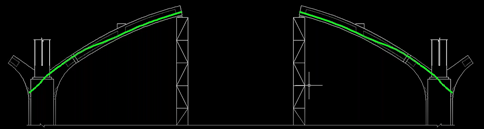
Two 19 strand PT tendons connecting end segments to thrust blocks
The next step, as shown in the figure below, is tow pre-stress the crown segment using two 19 strand post-tensioning tendons. The post-tensioning happens before the segment is set on the tower so that it could take place on the ground without running into any clearance issues with end segments.
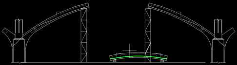
Two 19 strand PT tendons stressed in crown segments prior to setting on towers.
Then, as shown in the figure below, crown segments are erected, the closure pours were placed between the segments, and the duct connections were made for the post-tensioning ducts.
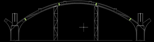
The closure pours were placed between the segments, the duct connections were made for the PT ducts.
Finally, four 15 strand post-tensioning tendons are placed through arch span for continuity and with symmetric configuration (one on each corner). They exerts pulling force on the arch and makes the arch rib compress against itself to add on more axial compression to the system. They also do not add on any prestress moment due to lack of any net eccentricity.
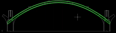
Four 15 strand PT tendons stressed through arch span for continuity.
Now when we look at the service level stress throughout the arch span after the post-tensioning, with the effects of dead load and live load included, we observe more axial compression, shown in the figure below. We are also further away from exceeding the maximum allowable tensile stress because the post-tensioning of the arch span has created beneficial compression that is able to resist bending.
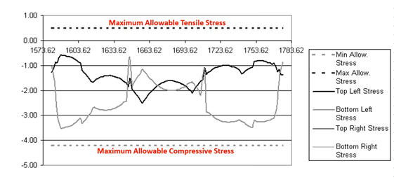
Stress distribution on the top and bottom surfaces of the arch span (after post-tension)
Editor: JC Sun
jsun@midasoft.com
Add a Comment