How to Model the Girder and Deck Connection in Composite Bridge? The way to simulate the connection between the girder and the deck will dep...
2 min read
Author: Yazeed AbuHassan
Publish Date: 25 Nov, 2020
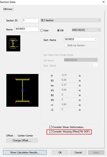
In typical engineering practices, engineers are used to having six degrees of freedom (DOFs) for modeling and analysis, three for rotations and three for translation. However, additional advanced beam elements can include other DOFs to represent the warping of an open thin-walled cross section. Such elements are not commonly available in professional software. (Article 1.2.6, G13.1 Guidelines for Steel Girder Bridge Analysis, AASHTO/NSBA, 2014). This has required engineers to model flanges as plates in order to obtain warping stresses. Midas Civil on the other hand has the 7th DOF warping feature which should save engineers a lot of time and effort and can grant warping related results directly from frame elements.
Understanding Warping:
Bridge elements undergoes the usual flexure and shear forces, as well as vertical deflections, and major axis bending rotations. According to Article 3.1.2 of G13.1 Guidelines for Steel Girder Bridge Analysis, the behavior of curved and skewed steel girder bridges can be broadly divided into two categories:
The Basics - Curved or skewed steel girder bridges, or both, experience the same effects of gravity loading (dead load and live load) as straight girder bridges (as described in Article 3.1.1)
Curvature and Skew Effects - Torsional St. Venant shear and warping normal stresses, flange lateral bending, load shifting, and twisting deformations.
In a curved girder, the torsion arises due to gravity loads are applied along the length of the girder and these loads are offset from a chord line drawn between the supports of that span. Due to this offset of the loading, a net torsional reaction is required at the supports to satisfy overall equilibrium of the span. And because I-shaped girders have low St. Venant torsional stiffness given the low torsional rigidity of sections, they carry torsion primarily by means of warping, unlike thin-walled closed cross sections where torsion is mainly resisted by a set of shear stresses distributed around the cross section. (Article 3.1.2.1) Torsion is caused not only by curvature but by overhang loads, eccentrically located live loads, and construction loads.
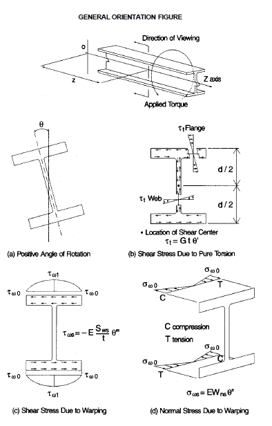
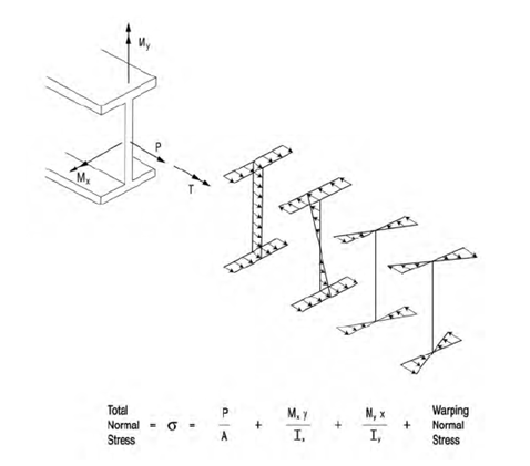
Figure 4.1 in AISC Steel Design Guide - Torsional Analysis of Structural Steel Members.

Figure 3.1.2.1-1 of (G13.1 Guidelines for Steel Girder Bridge Analysis, 2nd Ed.) Illustration of the general I-girder normal stresses, which can occur in a curved or skewed I-shaped girder.
Is Warping Calculated by Midas Civil Reliable?
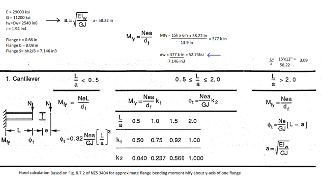
In order to have this checked, a sample calculation of a 15' fixed end cantilever (fixed for translation and rotations in all 6 DOF's in addition to the 7th DOF for warping) with a 6" eccentric end force of 15 kips was applied on W14x53. Warping was calculated using both midas and hand calculated utilizing the NZS 3404 Design for torsion chapter. Results were then compared.
Hand Calculation:
Midas:
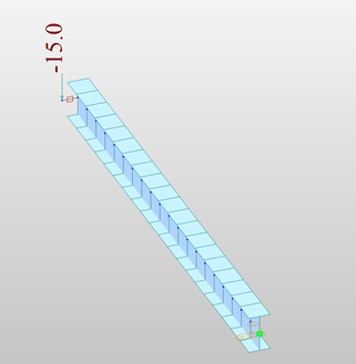
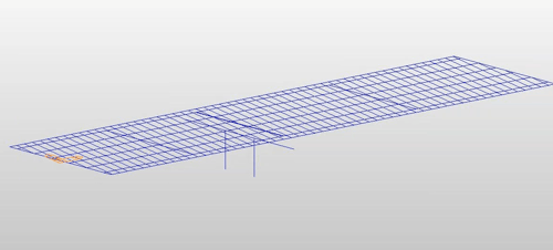
A 15' frame element with fixed ends and eccentric load of 15 kips
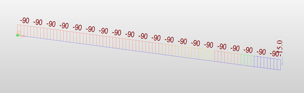
Torsion Diagram (kips-in)
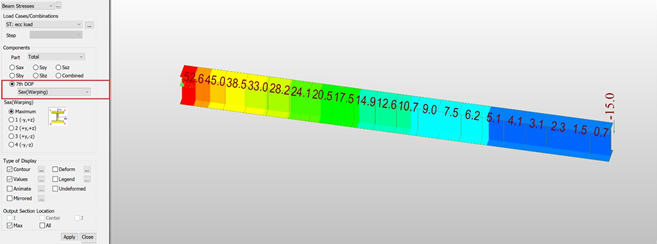
Warping Stress Diagram (ksi)
Midas reported warping stress = 52.6 ksi Vs 52.75 ksi in hand calculations
Error = 0.3%
This concludes that warping stress results in midas Civil are reliable.
Editor: JC Sun
jsun@midasoft.com
Add a Comment