Setting up links for bridge structure analysis is a very important step, yet often times it is implemented without too much consideration to...
5 min read
Author: Luis Vila
Publish Date: 7 Dec, 2020
This tip talks about different types of links that you can find in midas Civil and their applications. You may be wondering what are the implications of using one type of link compared to another, this tip will answer that for you and help you gain more confidence when choosing the link types.
Why do we need links for bridge models?
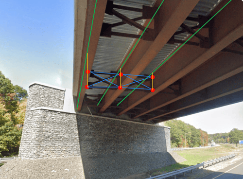
When we create, for example, a steel girder superstructure shown in the image below in midas, we essentially have beam elements for the main girders and elements for the cross-frame members. In reality, we have the web plate connecting the cross-frame to the girder. The software, however, does not know about the connection until we tell it so.
A steel girder bridge with cross-frame members connecting the girders. The green line indicates girder elements in Midas, blue indicates cross-frame members, and yellow indicates links.
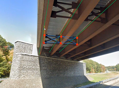
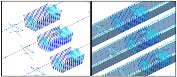
Shown in the image (left) below, at the top of the cross-section, we have the insertion points (green) for the girders. In midas Civil, the insertion point is where elements connect. Even though it looks like the nodes at the cross frames are touching the plate girder, they are not actually connected until we set up the link connecting the cross frame nodes with the girder insertion points. The links are shown in yellow in the image below (right).
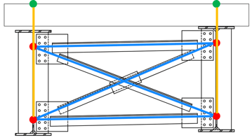
(Left) Cross section of part of the superstructure with cross-frames shown in blue, girder insertion points shown in green, and nodes shown in red. (Right) Links (yellow) that connect cross-frame elements to girder elements
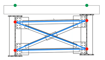
Another example is when modeling a truss bridge, shown below (left), with a cross-section, shown below (right), the deck is supported by the stringers which are supported by floor beams connected to the truss.

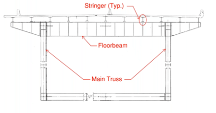
(Left) A truss bridge to be modeled in midas Civil, (Right) The cross-section of the said truss bridge.
Therefore, in midas Civil model, the links are set up to establish interconnectivity, as shown in the image below.
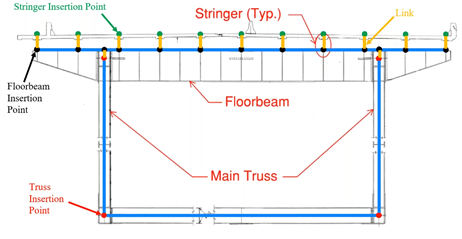
How the said truss bridge is represented in midas Civil grillage model with yellow lines indicating links.
What Are Types of Links in Midas Civil?
The types of links you can find in midas Civil can be summarized below:
Elastic Links
- Behave similar to an element
- User-defined stiffness to constrained DOFs
- Types of elastic links
- Elastic - Rigid
- Elastic - Compression/Tension Only
- Elastic - General
- Elastic - Multi-linear
Rigid Links
- Displacement constraint
- Constrained DOFs are assumed as rigid
Elastic links behave similarly to an element. In midas Civil, you can only connect two nodes with an elastic link. You are able to assign stiffness to that link as well.
What is Elastic Rigid Link?
It is one of the most used links. An elastic rigid link has infinite stiffness in all 6 DOFs and is used to simulate rigid behavior. You can typically find these links at the bottom end of the plate girders, where you link the girder bottom to the support node. They are also used for diaphragm connections, where diaphragms are connected to the girders.
What is a Compression/Tension-Only Elastic Link?
Compression/Tension-only elastic link has axial stiffness only. It is used for special configurations and soil structure interfaces, and it is the non-linear link. Therefore, iterative procedures are required to solve for this type of link. For example, for a structure with compression-only links, the software is going to consider all the links as active links and is going to find which ones are in compression and which ones are in tension. For those that are in tension, the software will remove them from the model and rerun the analysis. This iterative process will continue until it finds that all the remaining links are in compression. Having that in mind, and knowing the inherent linear nature of the influence lines used by moving load analysis, this type of link can not be used for moving load analysis due to its non-linearity.
What is a General Elastic Link?
The general elastic link is the type that gives you the most flexibility, where you can define the stiffness in all 6 DOFs. To calibrate the stiffness for the general elastic links to have the same effect as the rigid elastic links, the following procedure can be adopted. Two identical models are created, one with all the links modeled as rigid elastic links, and the other one with general elastic links assuming high stiffness in all DOFs. Compare the results between the two models and update the stiffness of the "high stiffness" general elastic links until you get similar results. This might take a few iterations, and you might need to increase the stiffness of the general elastic links until the two models get the same results. At that point, the assumed high stiffness allows the general elastic link to behave like a rigid link, and you may release or define the desired/known stiffness in the DOFs that are not "rigid".
What is Rigid Link? How to Use Rigid Link to Connect Girder and Deck Elements?
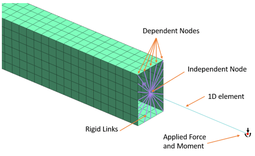
The definition of rigid links is in a geometric sense. It keeps the distance between the nodes that are constrained constant throughout the analysis and requires the definition of master and slave nodes. When the master nodes experience translation, the slave nodes are going to experience the same translation. When the master nodes experience rotation, the slave nodes are going to experience rotation as well as translation. One main difference between rigid links and elastic rigid links is that rigid links can connect multiple slave nodes to one master node while elastic rigid links cannot. It is also very important to note that the slave nodes are going to pick up and prioritize all the properties of the master nodes, therefore the support conditions of the master nodes are going to transfer and overwrite the existing ones of the slave nodes.
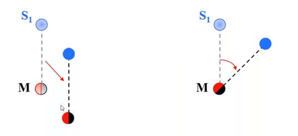
(Left) When master nodes experience translation, the slave nodes are going to experience the same translation. (Right) When master nodes experience rotation, the slave nodes are going to experience both translation and rotation due to the equal distance from the master nodes.
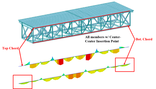
The typical application of using the rigid link is beam elements to plate elements transitions. For a tub girder bridge that was modeled with beam elements, its analysis results suggested that the bottom flange was experiencing buckling because of compression due to negative moments. Therefore, we want to further investigate how the bottom flange was buckling. Based on the beam element model, we created the tub girder with plate elements at the area of interest and used rigid links for the transition from beam to plate elements. We used the girder nodes as the master nodes, and nodes on the perimeter of the tub girder as slave nodes, as shown in the image below.
The transition from beam element to plate element to simulate a more detailed analysis results in a buckling tub girder bridge model. Shown in light blue are rigid links established between the beam nodes and nodes on the perimeter of the plate elements.
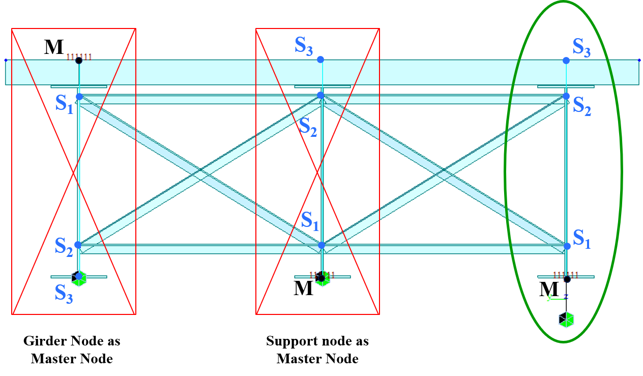
Therefore, going back to the original steel girder bridge with cross frames, how can rigid links indicate interconnectivity in its midas Civil model? The image below shows three examples of link applications, and two of the configurations are incorrect.
- The top node is defined as the master node as well as the insertion point for the plate girder. The three other nodes are slave nodes. The slave nodes, as mentioned earlier, are going to pick up the properties of the master node even though the bottom node was already assigned with a fixed boundary condition. The master node, however, does not have any support condition defined. This would lead to an error message from the software when starting the analysis: "[Warning] constrained degrees of freedom at slave nodes are automatically released."
- Support node as the master node. This also creates errors even though the software would not give error messages. In this case, when the master node is defined with a constraint, the constraint is carried out to all the slave nodes.
- Correct configuration has an additional node below the bottom of the girder node. This support condition is isolated from the master node, and the node is connected with the master node using an elastic link. The length of the elastic link is usually the thickness of the realistic bridge bearing being used, and the stiffness of the elastic link is the known stiffness of the bridge bearing being used.
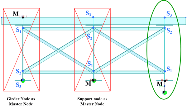 (Left) Incorrect boundary configuration where the master node is the girder insertion at the top. (Middle) Incorrect boundary configuration where the master node is the girder's bottom node. (Right) Correct boundary configuration where the master node is an extra node defined a distance below the bottom of the girder and the master node is connected to the girder bottom using an elastic link.
Editor: JC Sun
jsun@midasoft.com
Add a Comment