Detail of this Session This online technical seminar will introduce the FEM approach to consider soil-structure interaction for shored excav...
3 min read
Author: Parsa Heydarpour
Publish Date: 30 Jun, 2021
What is the Support of Excavation System?
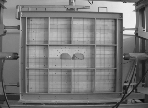
Support of Excavation (SOE) systems are temporary structures that allow us to do a deep excavation at vertical or near-vertical angles so we can minimize the earthwork that needs to be done. Figure 1 shows an example of the SOE system. The main goal when designing the SOE system is to prevent structural collapse, as well as controlling and minimizing displacement. The SOE systems can often be found in metropolitan areas with dense populations, and they are often surrounded by adjacent buildings and infrastructure systems. Disturbance in the soil would create damages in those surrounding structures, and soil disturbance is unavoidable during excavation work. Engineers and contractors are not able to completely zero out the disturbance, but by having a proper design they can minimize those disturbances. They can also minimize the differential settlements that produce cracks and damages to the buildings. When those are minimized, the strain and longitudinal forces would be minimized as well.
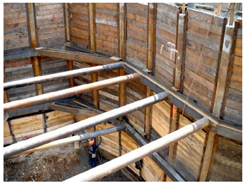
Figure 1. Example of an SOE system. (Image is provided by Parsa Heydarpour).
Why is the Support of Excavation Design a Complex Problem?
SOE design is a complex problem by nature due to the following reasons:
- Soil -structure interaction
- Depth of cut and groundwater
- Superimposed loads
- Seismic loads
- Vibrations
- Adjacent construction
Soil structure interaction would vary the way forces are applied on the cantilever or bracing system, which needs to be considered. Depending on the excavation location, water-related issues would also bring complexity. Another complexity is the soil's nonlinear material properties. Any method that does not consider the soil nonlinearity would not provide an accurate approximation of forces and displacements. Furthermore, in linear systems, loads can be superimposed to simplify the analysis, however, superimposing loads in nonlinear soil models would not work. Lastly, adjacent sources of vibration including seismic activities, metro projects, or machinery are needed to be considered.
Therefore, for such a complex problem, we need to make sure that the solution method considers these sources of risk and appropriately accommodates each of them.
What are Conventional Design Methods for the Support of Excavation?
Conventionally, the SOE systems are designed using closed-form solutions and the limit equilibrium methodologies. For many of the complexities mentioned above, the solutions can not meet those variabilities. However, the advent of the finite element method and the increased computational capacity of modern computers have enabled the modeling of complex geotechnical problems with a myriad of variables and conditions. As well as getting much more accurate results. In commercial FEA software such as Midas GTS NX, engineers are able to consider dewatering, simulate multi-stage excavation, define interfaces, and define soil-structure interaction, etc. As a designer, I believe we need to better use the capabilities and technologies to better approximate the structural behavior.
One example of design complexity that can not be approximated by the conventional method is the arching effects. What is the arching effect in the support of excavation design? The arching effect is due to the difference in stiffness of structural members. The difference in the material stiffness would create a horizontal arching. Similarly, when you are looking at a pile in the vertical direction, the places where there are struts have a much higher stiffness. This stiffness difference would create differences in the distribution of forces, which contributes to vertical arching. The crude conventional method does not capture these arching effects. However, in FEM using nonlinear material models, arching effects would be much better approximated.
Below shows an example of the SOE design done by Midas GTS NX, a FEM analysis tool for 2D/3D models. It also shows how the FEM results obtained in Midas GTS NX compares with the conventional shoring suite results.
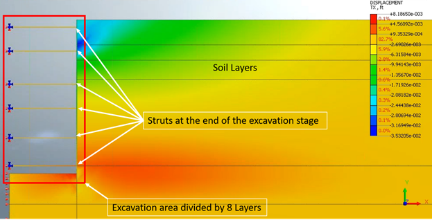
Figure 2 and Figure 3 show the displacement plots of an SOE analysis result. Highlighted in red is the excavated area which is divided into 8 layers for 8 corresponding excavation stages. The effect of excavation stages is simulated using the construction stage definition in Midas GTS NX, in which the excavation layer at each stage is deactivated consecutively.
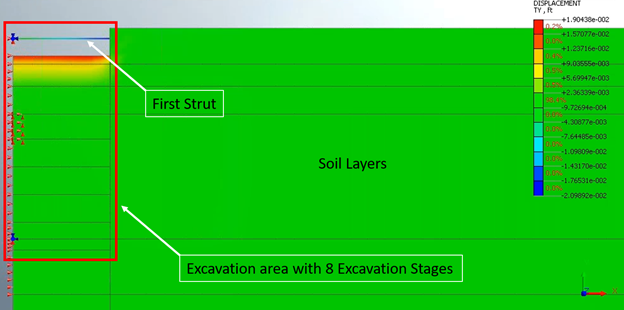
Figure 2. Displacement (vertical) plot of the 1st stage of the excavation stages of the SOE system considering soil nonlinearity. (Model is done in Midas GTS NX by Parsa Heydarpour).
Figure 3. Displacement (vertical) plot of the 8th stage of the excavation stages of the SOE system considering soil nonlinearity. (Model is done in Midas GTS NX by Parsa Heydarpour).
We are also interested in the force being developed in the beam struts. Figure 4 shows the axial forces of each strut at each stage. The maximum axial force at the strut is 20.67 kips (found at the bottom right of the table) from this analysis.
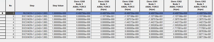
Figure 4. Axial forces of each strut at each excavation stage. The maximum axial force (20.67139 kips) can be found at Element 5363 at stage 8. The result is generated in Midas GTS NX by Parsa Heydarpour
Figure 5 shows the shoring suite results. The maximum horizontal force obtained in this case is 27 kips.
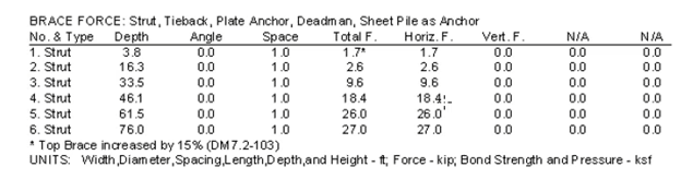
Figure 5. Shoring suite results of the same example SOE design. The maximum horizontal force can be found at the deepest strut at 27.0 kips.
Comparing the maximum axial/horizontal force at the struts, a large difference (25%) is observed. The 2D FEM model in Midas GTS NX has considered the excavation stages and the nonlinear material properties, which the shoring suite method has not. And this has resulted in a significant difference in the analysis results.
You can find how the example model is set up in Midas GTS NX in Webinar: Contrasting SOE Design Methodologies and Implications
Editor: JC Sun
jsun@midasoft.com

Add a Comment