


Click here to download the model and wizard files Purpose of the Training The purpose of the training is to show the most effective ways to ...
3 min read
Author: Ahmed Rageh, PhD, PE
Publish Date: 28 Sep, 2022
The midas model is for a multi-channel prestressed girders bridge 30 ft span and 24.75 ft width. The bridge is composed of 9-channel prestressed girders placed side by side. The bridge was modeled with frame elements for the girder's webs and plate elements for the girder's flange. Bridge dimensions and midas models are shown below.
Figure 1: Bridge Details
Figure 2: Midas Model
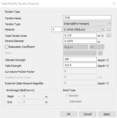
Strands material is ASTM A416-250 low relaxation, and tendon properties are as follows:
- Diameter: 0.4375 in
- Area: 0.115 in2
- Ultimate strength: 250 ksi
- Yield strength: 212.5 ksi
The figure below shows midas defined strands material and property.

Figure 3: Strands defined material and property
Before creating tendons profile, renumbering girders webs frame element is necessary to allow for using the MCT easier. To do so, the frame elements were numbered as follows:
- Girders will have numbering starting with thousands. For example, 1000 for girder 1 and 5000 for girder 5.
- Girder number followed by web numbers with hundreds, either 100 for the 1st web or 200 for the 2nd web.
- Then the midas auto numbering will follow.
- For example, to renumber girder 6 web 2 frame elements, we will start with 6201 in the midas auto-numbering tool.
- Now by activating the girder 6-second web frame element only, we can renumber them as shown in the figure below.
- Following the same procedures, we can renumber all girder's web frame elements.
Figure 4: Renumbering girder 6 web 2 frame elements
Figure 5: Renumbered girders webs frame elements
Next step, we will define one tendon profile then we will copy that to all girders with the MCT tool.
- We will define the 1st strand of girder 1 web 1 “we will give the strand a name CH1-W11,” meaning channel 1 web 1 strand 1.
- The assigned elements will be 1101 to 1130. The girder web has a total of 30 frame elements along the girder length.
- The eccentricity of that strand measured from the web centroid was calculated as -4.5741 inches in the Z direction.
- The eccentricity of the strand in the X and Y directions is 0.00.
Figure 6: Defining girder 1 web 1 first strand (CH1-W11)
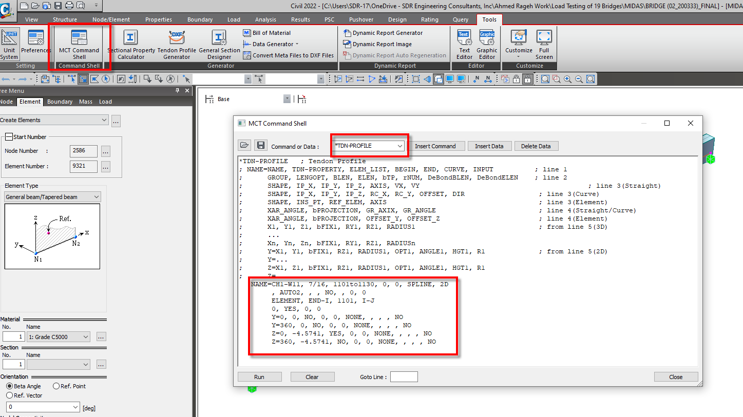
Now we can use the MCT tool to copy tendon profile CH1-W11 to the other 3 remaining tendons in girder 1 web 1 (CH1-W12, CH1-W13, and CH1-W14).
- The vertical distance between tendons is 2 inches.
- We will copy the CH1-W11 definition with the MCT tool and change the name and Z coordinate by 2, 4, and 6 inches.
- Go to the MCT tool and write in the Command or Data “*TDN-PROFILE”, then click insert data. The following screen will show up, and we will see the definition of CH1-W11 tendon.
Figure 7: MCT Definition of tendon CH1-W11
- Now we will copy the tendon definition TWO times to modify it to the rest of girder 1 web 1 tendons. We will change the code as follows:
- 1st code portion change: Name to CH1-W12,
Z coordinates to -2.5741 = -4.5741 + 2 inch upwards - 2nd code portion: Name to CH1-W13,
Z coordinates to -0.5741 = -4.5741 + 4 inch upwards - 3rd code portion: Name to CH1-W14,
Z coordinates to 1.4259 = -4.5741 + 6 inch upwards - After changing the coding lines, click run.
Figure 8: Copying tendon CH1-W11 to the remaining tendons in Girder 1 Web 1
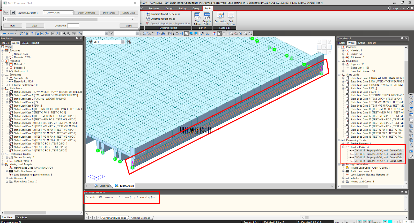
- After clicking run, make sure that you are getting no errors in the message window and the new tendons are shown in the tree menu.
Figure 9: Girder 1 Web 1 remaining tendons defined with the MCT tool
- Now we will start copying Girder 1 Web 1 tendons to Girder 1 Web 2 with the MCT tool. In the MCT tool, click the “Clear” button, then click Insert Data. After clicking run, ensure that the Command or Data is still “*TDN-PROFILE.”
- Now we can see the definition of Girder 1 Web 1 4 tendons. To match Girder 2 Web 2 elements, we will change the following in the 4 coding segments.
- Names to be: CH1-W21, CH1-W22, CH1-W23, and CH1-W24
- Elements from Girder 1 Web 1 frame element numbers 1101to1130 to Girder 1 Web 1 frame element numbers 1201to1230.
- Change the element end from Girder 1 Web 1 frame element 1101 to Girder 1 Web 2 1201.
- Click Run and Girder 1 Web 2 tendons should be modeled.
Figure 10: Girder 1 Web 2 tendons defined with the MCT tool
- To copy strands to the remaining girders webs, we have 2 options:
- Change the current MCT 4 code segments to match each girder web one by one.
- Or, we can copy these 4 code segments 16 times, modify names and frame element numbering to match the remaining girder's webs, then click Run.
- Names to be: CH1-W21, CH1-W22, CH1-W23, and CH1-W24
- Elements from Girder 1 Web 1 frame element numbers 1101to1130 to Girder 1 Web 1 frame element numbers 1201to1230.
- Change the element end from Girder 1 Web 1 frame element 1101 to Girder 1 Web 2 1201.
- Now let us define the Tendon Prestress. We can also define them from the Midas interface or the MCT tool. However, we must define at least 1 from the midas interface window to get the correct coding segment. The prestressing force is calculated to be 19.55 kips.
Figure 11: Defining prestressing force for tendon CH1-W11
- From the MCT tool, Click Clear.
- From the MCT tool, in the Command or Data, type “*TDN-PRESTRESS,” then Insert Data. The defined prestress force code portion could be seen in the MCT Tool.
- Copy the tendon CH1-W11 defined prestress force code portion 7 times (number of remaining defined tendons).
- Change the name to match the defined tendons names, then click Run.
- The defined tendon prestress force should now be defined.
Figure 12: Defining tendons prestressing force with MCT tool
Co-Author: Sarah ElSawah, MS, PE, Structural / Bridge Engineer at SDR Engineering Consultants


Add a Comment