Author: Seungwoo Lee, Ph.D., P.E., S.E.
Publish Date: 8 Aug, 2022
Unsymmetric Section Analysis
There are many programs that can check the strength of members with axial force and moment. However, not many programs can check the serviceability and strength with prestressing. In this and the next article, we will discuss the details of these two cases.
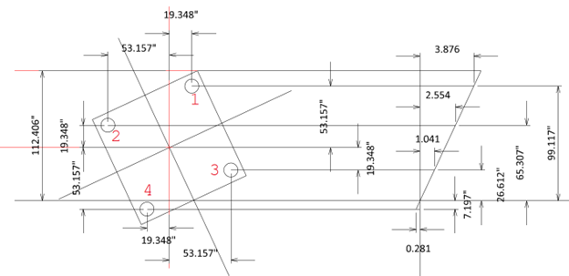
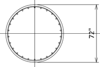
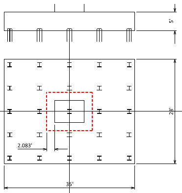
Assume we have the following unrealistic section.
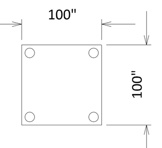
Four #5 (0.31 in2) rebars are located at each corner with a 10” cover (face to rebar center). Allowable stresses for concrete and reinforcement are fca = 0.4(fc’ = 4 ksi) = 1.6 ksi, fsa = 0.6(fy = 60 ksi) = 36 ksi, respectively.
At the service limit state, our analysis shows P = 6600.24 kips, Mx = -8777.2 ft-kips My = -4016.5 ft-kips.
Our question is, is this section works at the service limit state?
It should be easy to check if (1) there is no axial force and (2) the moment is only one direction. Other than the circular section, checking the serviceability for the general section is not a simple task.
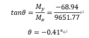
Step 1) Check the moment direction.
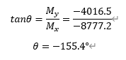
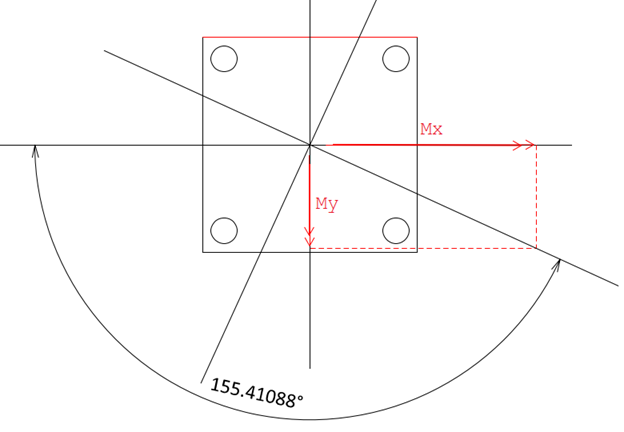
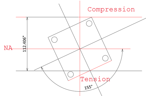
Our problem is equivalent with resultant moment M = √(Mx2+My2) = 9652 ft-kips is acting 155.4° from the horizontal axis, counterclockwise direction.
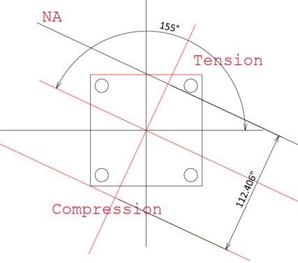
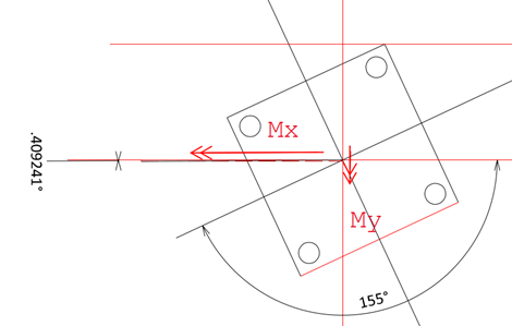
Step2) Assume the rotational angle and location of the neutral axis.
Assume section rotation angle as 155° counterclockwise and neutral axis location is 112.406”.
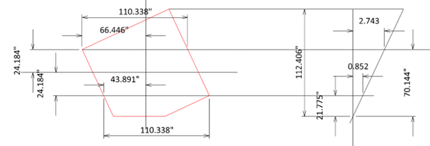
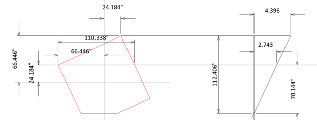
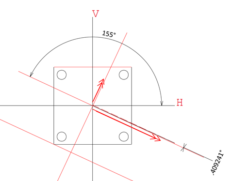
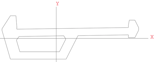
Step3) For ease of understanding, rotate the section 155° in the clockwise direction.
step4) Check the stress for concrete and reinforcement.
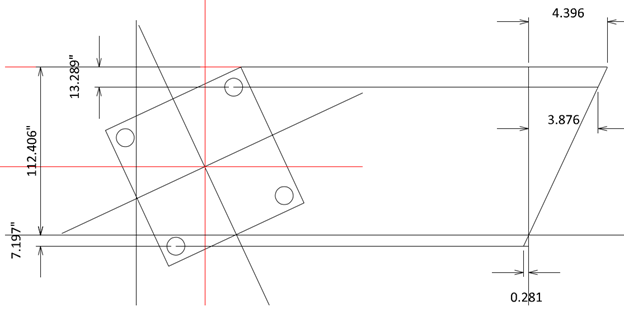
Assume top concrete fiber reaches the allowable limit.
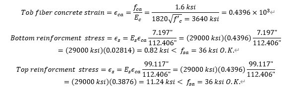
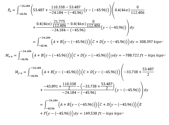
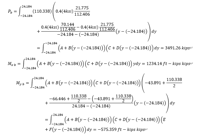
Step5) Concrete
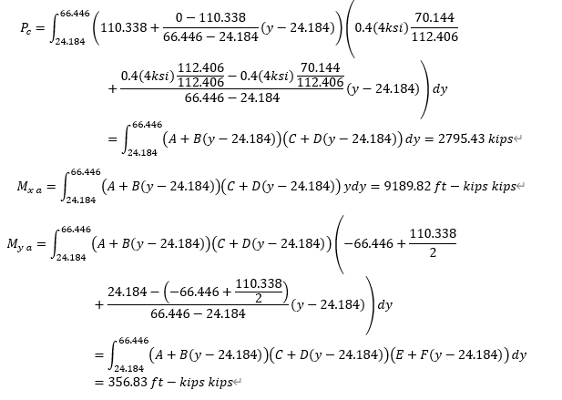
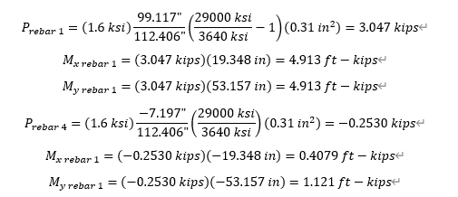
Step6) Reinforcement
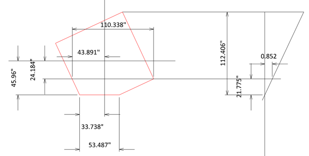
Step7) Summary
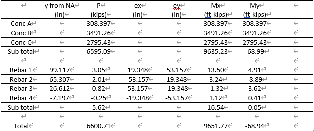
These moments are for the rotating axis, and it would be convenient if we convert these moments into the horizontal and vertical axis.
Step 8) Convert to horizontal and vertical axis.
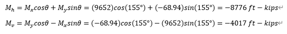
These moments are matched with what we wanted to check and this section would work at the service limit state.
Discussion
- In this calculation, we assumed the rotational angle and location of the neutral axis. The question is how to assume these two values. We need some kind of iteration.
- We may consider using the optimization technique; however, we need iteration anyways at behind. Also, convergence cannot be guaranteed with irregular shapes.
- We can consider this problem as a simultaneous equation problem. We can find P, Mx, and My with given stresses at three locations.
- In this simple example, the angle difference is only 0.41°. This is true only for these very simple sections. In the irregular sections, this difference is huge and results in convergency issues. This will be discussed in the next article.
- The calculation is voluminous, but we have no problem with computers.
- In this example, integration is applied to calculate concrete portions. In real design problems, vector analysis is handy.
Add a Comment