
The midas model is for a multi-channel prestressed girders bridge 30 ft span and 24.75 ft width. The bridge is composed of 9-channel prestre...
3 min read
Author: Yanling Leng
Publish Date: 5 Jan, 2022
Multi-span bridges composed of simple-span precast girders with continuous deck and diaphragms at interior supports have been a popular solution since the 1960s. State DOTs have employed various details and design methodologies. Understanding the details and designs of the continuity connections is critical for successfully modeling this type of bridge.
According to the AASHTO WSDOT Questionnaire: Prestressed Girder Design Criteria (2013) and a survey conducted by the author, the details and designs of continuity connections can be grouped into two categories.
Category #1: Design a series of simple spans for all loads. The slab (with or without diaphragms at interior supports) is continuous over the interior supports but ignored in girder design.

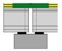 Figure 1 Category 1: Design a series of simple spans
It is noted that Midas Civil always internally considers the partial fixities as pinned conditions. Since the deck acts more like a hinge, it does not carry a significant flexural stiffness. When Midas Civil Pre/Post-Tensioned Composite Girder Bridge Wizard is used to build a model, given continuous checkbox unchecked, Midas internally introduces hinges at all internal support locations, by means of beam end release, such that moments and shears get modeled for simple span for all dead loads and live loads.
Category #2: Design as simple for the non-composite dead load (girder & slab weight), continuous for the composite dead load (railings & FWS), and live load. And there are two sub-cases. Sub-case 1 replaces temporary supports with permanent supports over the pier. The disadvantage of this method is that it needs additional temporary supports or more cranes during construction, which could be difficult and costly when crossing rivers or traffic. Hence, it is usually implemented in post-tensioned continuity connections. Sub-case 2 connections are common in practice. Current AASHTO Specification falls into this type as it is an easy construction method. However, the continuity connections' behavior and load transfer mechanism make the bridges behave differently from analysis assuming idealized pin or roller supports. Some conventional modeling approaches treat double bearings as single bearings for simplicity, and the results tend to be conservative. System transformation is realized by setting the deactivation of temporary bearings and activation of permanent bearings.

Figure 2-1 Category #2 sub-case 1: single bearing

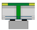
Figure 2-2 Category #2 sub-case 2: double bearings
Since slab concrete is usually poured before continuity connections, the weight of the wet concrete slab is the non-composite dead load. Midas Civil Pre/Post-Tensioned Composite Girder Bridge Wizard internally considers wet slab concrete as a non-composite dead load when a continuous checkbox is checked. Specifically, the Wizard assigns a dummy material with a weight density of zero to the concrete slab. Wet Concrete Load, a distributed load equivalent to the weight of the wet slab concrete, is applied to the model in the non-composite stage. Wet Concrete Load is deactivated when the simple spans are made continuous.
Alternatively, if the wet concrete slab is a composite dead load, the slab is cast after the composite action has been achieved. The wet concrete slab should not be deactivated when simple spans are made continuous.
Due to time-dependent effects, the girder ends tend to camber upward even after continuity is completed. While the cast-in-place diaphragm and slab tend to keep the girder ends from rotating, which results in a positive restraint moment in the girder over the piers. Per AASHTO LRFD Specification (Edition 9) Section 5.12.3.3. 2. The bridge shall be designed for restraint moments, except as allowed in Article 5.12.3.3.4.
Midas Civil makes the computation of restraint moments for the bridge easy. Refer to the webinar: Refined design and load rating for local bridges
Some States employ a conservative approach: design as simple spans for positive dead load and live load moments, continuous for negative live load, and superimposed dead load moments over the pier. This design moment/shear is the envelope of categories #1 and #2, therefore most conservative.
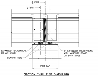
For existing multi-span bridges designed and detailed as a series of simple spans, experience has repeatedly proven that deck joints in these bridges cause problems. It has been evident to bridge designers that converting simple spans to continuous bridges to eliminate the joints is a desirable solution. A preferable solution to the full continuous bridge for live load conversion is to make the deck slab continuous but allow the girders to function as simple spans. A detail that will permit this has been successfully used is shown in Figure 3.
Figure 3. Method of eliminating pier deck joints in existing simple spans prestressed girder bridges
The detail shown in Figure 3 is similar to Figure 2-2, but the only live load is applied on the continuous bridge, and the deck only provides negative moment resistance.


Add a Comment