This tip talks about different types of links that you can find in midas Civil and their applications. You may be wondering what are the imp...
2 min read
Author: Luis Vila
Publish Date: 10 Dec, 2020
For structures with stability issues, one way to check which specific link is causing the problem is start with a constrained model and begin relaxing its DOFs gradually. When you are releasing the DOFs and when you are running into stability issues, you would know which link release is causing that instability.
However, you may have a bridge structure that is stable but not behaving the way it was intended. To understand structural behaviors like this, verifications are needed. This tip talks about how to verify your bridge links, and how seemingly trivial definitions like insertion points and beam end release can cause big variations in bridge structural analysis results.
What is Beam End Release? Example: Simply supported beam
For a simply supported beam, you may have the link properly defined but you could end up getting unexpected result without careful validation. For the simply supported beam below, we are seeing some negative moment at the end. This is not what we expect to see in a simply supported beam, and is due to the support not being at the CG (centroid) of the section. However, if you add beam end releases, the negative moments at the ends will drop to zero
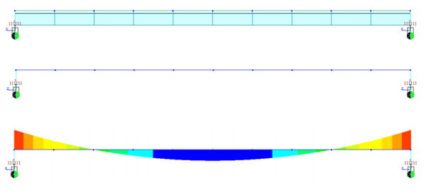
Bending moment diagram of a beam not supported at its ends' CG.
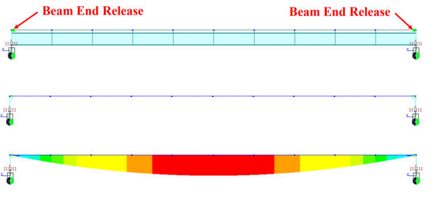
Bending moment diagram of a beam not supported at its ends' CG, but with beam end release applied.
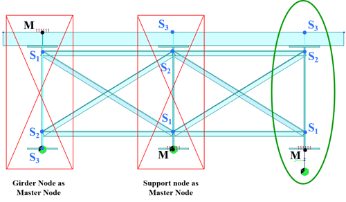
This is because when we use offset insertion point, midas Civil implicitly defines a link between CG and the offset insertion point. This link would result in the issue explained above.
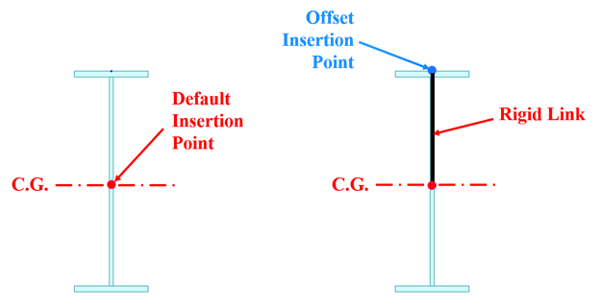
A rigid link is implicitly defined between CG and the offset insertion point without any user definition.
Here we have 3 cases. The first one has the insertion point at the CG of the section, and we obtain the expected bending moment diagram for simply supported beam. The second and third examples have the insertion points at the top and the bottom of the sections. We observe negative moments at the beam ends as soon as we have insertion points not at the CG of the section. However, when we add beam end releases for the second and the third case, we then obtain the identical results for the three cases.
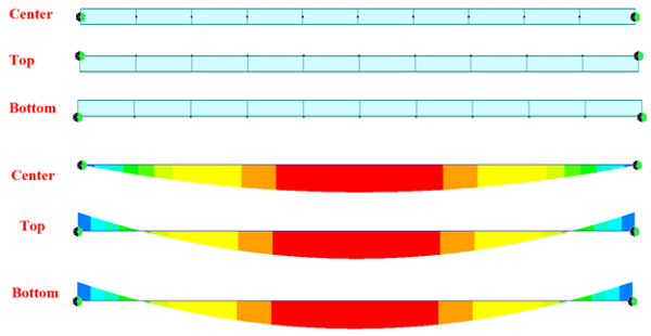
Bending moment diagrams of the three cases.
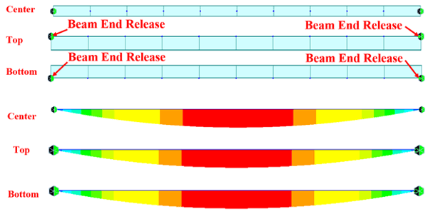
Bending moment diagrams of the three cases with the applications of beam end release.
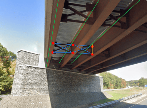
How does Insertion Point Affect Analysis Results? Example: Truss Bridge
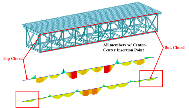
Another validation example is for the analysis of a truss bridge. When we are looking at the member forces, we realized that the force at the bottom cord does not seem right, as shown in the figure below.
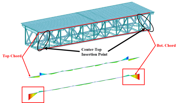
The bending moment diagrams of the top and the bottom chord of a truss bridge that raised our attentions.
We expect to see zero moment the ends of the bottom cord, but we were getting large amount of moment instead. It took us a while to figure out what was the cause for it because we had the model properly defined. We realized that the insertion point at the diagonals was defined at the top, rather than at the center of its section. Therefore, we changed insertion point of the diagonals to center and immediately noticed the difference in the moment diagrams, as shown below.

The bending moment diagrams of the top and the bottom chords after we have modify the diagonals' insertion points.
The offset insertion point in the diagonals was also significantly affecting the magnitude of the bending moments. As shown in the figure below, we obtain more than 5 times higher moment value with diagonals defined with center-top insertion point.
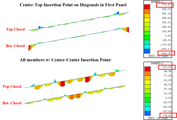
The bending moment diagrams of the top and the bottom chord of the truss bridge with different insertion point locations for the diagonals.
Editor: JC Sun
jsun@midasoft.com

Add a Comment