
Purpose of the Webinar Load Rating and Rehabilitation of the New River Gorge Bridge This webinar discussed the methods used for the analysis...
3 min read
Author: MIDASoft
Publish Date: 27 Dec, 2021
And here we reached the end of this series. So far, in the first part, we introduced some of the most relevant aspects of tunnel design, we discussed the types of procedures commonly used such as Open Cut and Cover Method, The Sequential Excavation Method (NATM) and a few others. We described some considerations that must be taken into account, the different design methodologies, the hypotheses that must be defined by structural and geotechnical engineers, and finally the results to be reviewed will be discussed once the analysis has been carried out with the element programs.
In the second part, we showed how to model the lining of a tunnel from the structural point of view, the procedure to define the section, the boundary conditions, the application is presented and the results obtained from this type of analysis. We also delved into the relevant aspects of the modeling of tunnels in 2D. The tools that the midas FEANX software has to generate tunnels sections are shown easily considering structural elements such as rock bolts and shotcrete, and it is also shown how to import geometries complex from AutoCAD. Finally, comparisons of the axial forces and the bending moments obtained for variations in the excavation procedure and the spacing between the structural elements of the support system were carried out.
In this final part we will be wrapping up the entire process and show how to go from a two-dimensional model to a three-dimensional model, the tools that the program has to evaluate if the geometry was made correctly and to define meshes for solid elements, as well as the options that the program has to simulate support elements such as metal profiles and shotcrete, using 1D and 2D meshes. We will also show comparisons between the 1D, 2D and 3D models. Subsequently, some of the wizards that the program has to execute analysis in a simple way will be shown and some advanced cases elaborated with midas FEANX will be shown.
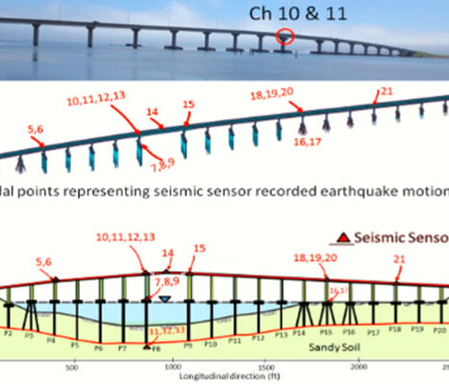
Three-dimensional models are especially useful when the terrain geometry is irregular in the tunnel direction, as well as if the geometry of the tunnel or of the underground work analyzed is not symmetrical and has an important three-dimensional component. Ground displacements associated with tunnel excavations occur in vector directions X-Y-Z, thus to accurately represent ground behavior during tunnel excavation processes, detailed 3D numerical analysis is vital. Modeling tunnels in 3D is becoming more attractive because of limitations of the 2D modeling and because it captures the response of tunnel excavations more accurately.
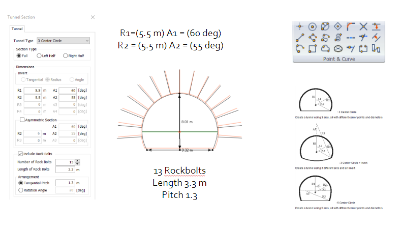
You can define the tunnel section and terrain as in 1D and 2D models
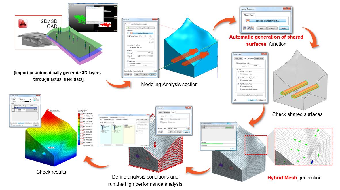
You can easily convert a two-dimensional model into a three-dimensional model using the "Protude" menu which allows you to extrude 2D elements following a straight (Extrude) or curved (Sweep) path. You can also easily define the progress of the tunnel by repeatedly copying a surface, with which the tunnel will be cut. Our software has tools that allow you to verify the connectivity between the elements that make up your model. The following figures show an example in which the geometry is initially disconnected, but it is solved using the Auto Connect command.
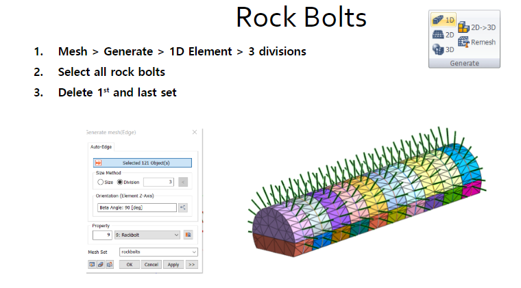
Midas FEANX has an extensive database, with which you can define the section of your support elements quickly and easily, on the other hand, it allows simulating two-dimensional support elements (shotcrete and walls) using structural elements such as Shell. You can make three-dimensional meshes using hybrid and tetrahedral elements. You can do the meshing independently or generate the mesh of several elements at the same time. To facilitate the connection between 3D and 2D elements, Midas FEANX has a tool that allows generating 2D meshes based on the faces of the 3D meshes already generated. In this way, the coatings can be easily generated. As for the 1D elements, the program has special structural elements (Embedded beam & Embedded truss), which do not need to share nodes with the solid elements in which they are embedded, with these elements you can easily simulate rock bolts.
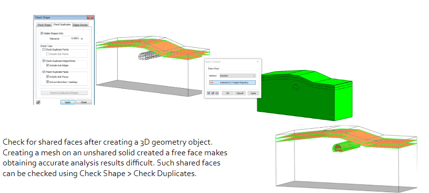
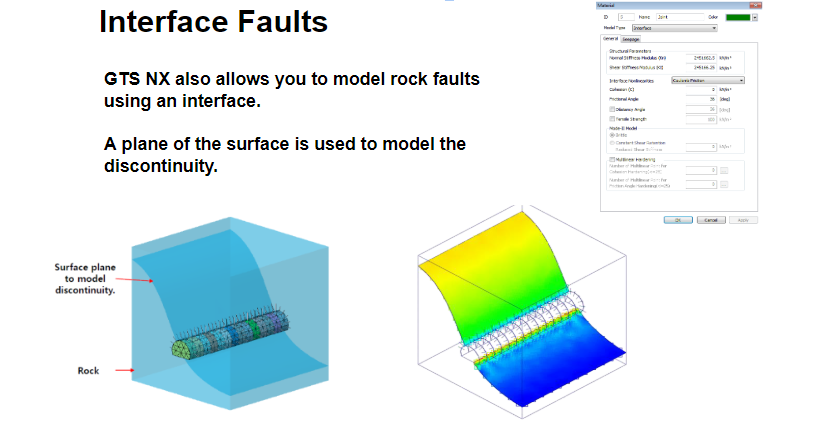
When you have complex models in which there are internal solids, you can verify the correct connection between the faces of these elements using the advanced meshing functions. It is possible to simulate the presence of geological discontinuities in the ground through interfaces, with them you can simulate the filling material of the discontinuity and the normal and shear stiffness, as shown in the following figures.
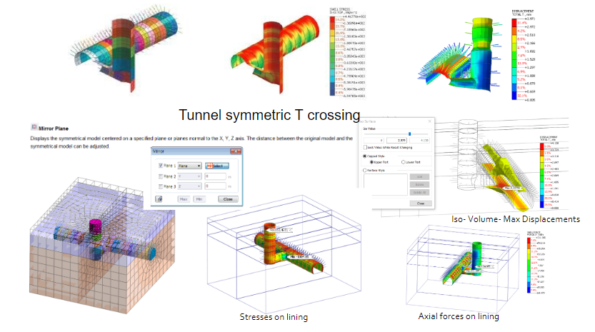
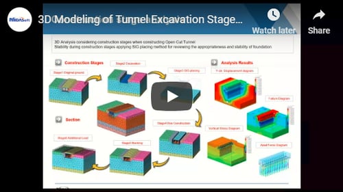
In the three-dimensional analyzes any constructive procedure can be simulated, without a limit number of analysis stages, results are obtained for each of them. Some very important and very helpful results to evaluate the safety of the tunnel are those corresponding to the state of the material and the safety factor. The state results allow to evaluate the plastic points, loading and unloading points and hardening points. The safety factor results allow evaluating the relationship between the shear stress in the ground and the failure stress corresponding to the Mohr coulomb criterion. In the areas where the FS is less than 1.2 they coincide with the areas of plastic points. Cuts can be made on specific sections of the model, as well as animations to visualize the results throughout the various stages of analysis. Some other tools for displaying the results are shown in the following figures.
Finally, the program allows you to make a dynamic report, in which you can put all the information you require. Save the model information before analysis and the result information after analysis as a 3-dimensional PDF document. Adjusting the 3D view on the PDF document and checking the cross-section information, similar to the operations in the program, is possible. Hence, the 3D model / analysis result information can all be checked on one PDF document without the model / result files.
Finalizing this series, we can continue to apply part 1 and part 2 and now add to it based on what we learned about 3D. Haven't started yet? Get started, and walk through the series to finalize your 3D tunnel. Get your free FEA NX license and get started on modeling >>
Add a Comment