Tunnel projects are a rather unique challenge. That's because, tunnels to put it loosely (no pun intended), are underground/buried roadways ...
2 min read
Author: MIDASoft
Publish Date: 27 Dec, 2021
In the first part of this short series, we introduced tunneling projects with a structural approach, we also went into detail about some of the many methods used during these types of projects such as Open Cut and Cover Method, the Sequential Excavation Method (NATM) and a few others. In part two of this series we will dive into more of the 2D aspect tunnels with ground elements.
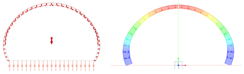
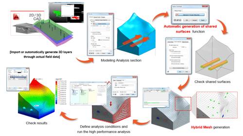
For tunnel modeling, considering the ground (2D analysis) presents a more geotechnical approach which, in contrast with the structural analysis, focuses more on the uncertainty of construction step and material itself, rather than the load. Therefore it is important to understand physical state inside the ground. As a result, for ground analysis, solid elements need to be used in modeling to reflect the ground shape and construction situation; and non-linear isotropic materials and in-situ stress states need to be considered to reflect the actual on-site conditions as much as possible. The analysis procedure is similar to that of 1D, since the section geometry must be generated, although in this case the terrain geometry is also included. The finite element mesh is made, then the boundary conditions and loads are defined. Unlike the 1D analysis, in these analyzes the excavation procedure can be considered by means of an analysis of construction stages, which must be defined. Finally, the analysis is run and the results are obtained.
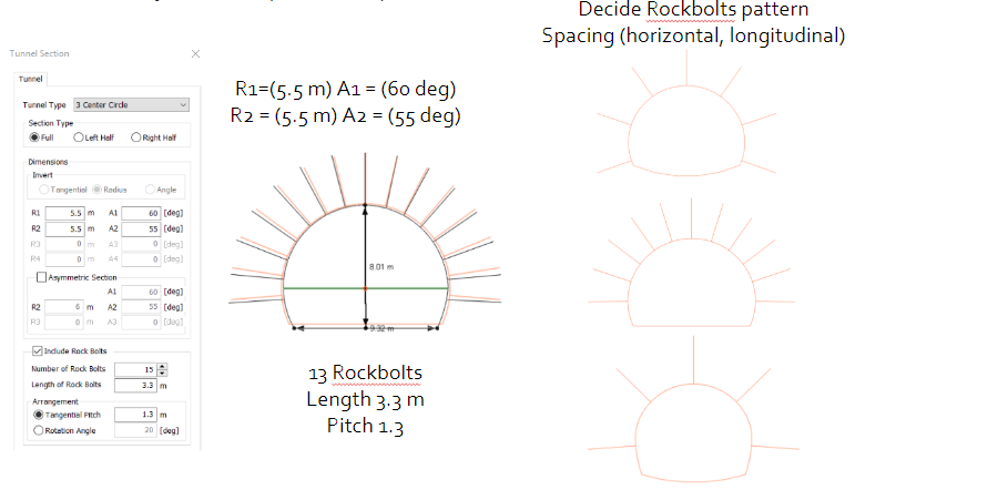
The section can be defined as in the 1D analysis and additionally elements of improvement (Rock Bolts) can be considered.
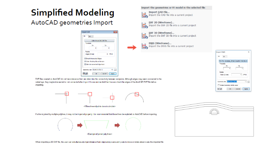
You can also import the section from a CAD file, using the Import command.
The mesh of the coating is generated in the same way as 1D analysis. Meanwhile the mesh of the terrain can be generated with different types of finite element.Select between a triangle, quadrilateral or both. Quadrilateral meshes provide a more stable analysis, but for complex geometric shapes it is better to generate a triangular mesh.
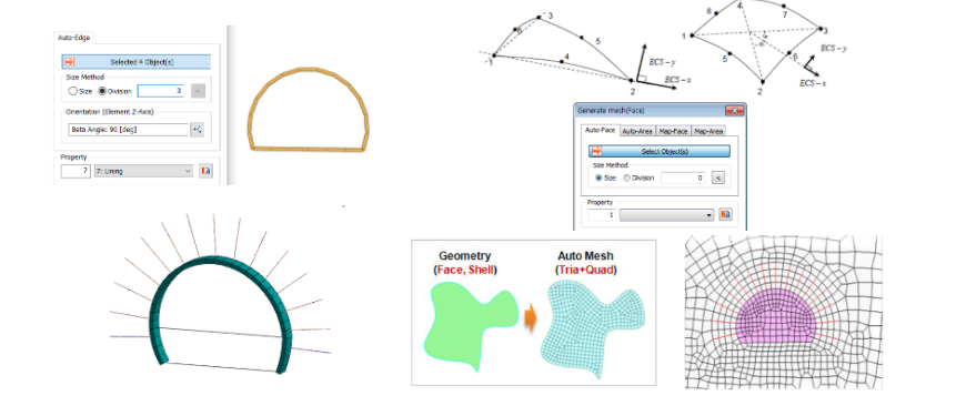
For best results, the finite element mesh should have a better quality (smaller size) in the areas of interest, which in this case will be in the vicinity of the tunnel. For this, FEA NX has the “Mesh size control” tool, which allows defining the required size in certain areas, as well as generating size gradients as shown in the following figures. On the other hand, a different material can be assigned to each soil stratum, which allows considering the complete stratography of the terrain.
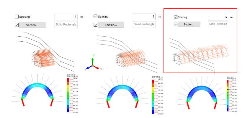
Once the analysis case has been defined and the analysis has been executed, the results of the model can be reviewed. The following figures show the comparison between results obtained for a tunnel excavated with a full section and another one executed with Bench Cut. With 2D analysis, the simulation of different spacing between the support elements of the tunnel can be performed by considering the spacing. On the FEA NX, spacing is used to calculate the stiffness of the element and output the member force per each element. The following figures show a comparison of the axial loads on the support elements when considering different separations
Moving into a bit more advanced portion, we can continue to apply part 1 of this series and now add to it based on what we learned about 2D. Haven't started yet? Get started, and stay tuned to finalize your 3D tunnel. Get your free FEA NX license and get started on modeling >>

Add a Comment