Author: Seungwoo Lee, Ph.D., P.E., S.E.
Publish Date: 5 Jan, 2022
Creep Analysis 3
We have gone through two different approaches by Dr. El-Badry so far. You can find the previous articles via these two links: Creep Analysis 1, Creep Analysis 2.
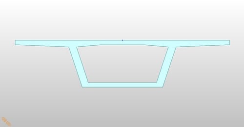
For creep analysis, the most common problem in the real-world design is continuous girders built as span by span. This example is very well explained by Dr. Ghali et al. (Concrete structures, Stresses, and deformations, 4th ed., CRC press, Example 4-2). Dr. Ghali et al. explained this problem by flexibility methods. The author will solve this same problem by stiffness methods. The programs do the matrix formulation and equation solve, and only the load matrix formulation and post-processing are our concern in the stiffness methods. Two MIDAS files are attached.
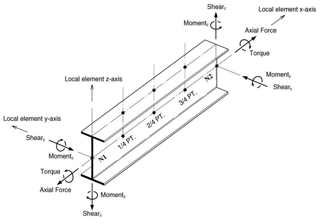
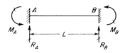
First, the author wants to define the sign convention for member forces clearly.
Sign Convention
Fixed end forces are the same for members 1 and 2.

At time t1, the member end forces due to uniform load at span two can be calculated below. Note that Ec(60)/Ec(7) = 1.26. (MIDAS file ex.2A)
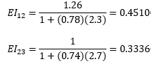
Analyze two-span continuous beam for these member end loadings. Note that the section properties are shown below, and the loading directions may not be identical for each program. (MIDAS file ex.2B)
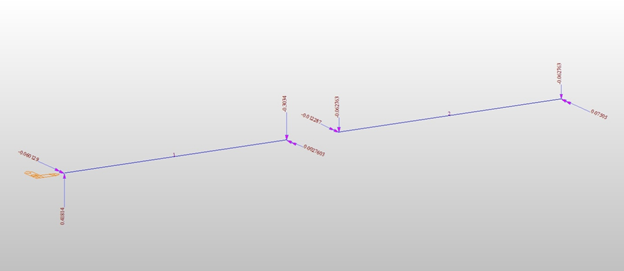
Loading Diagram (ft, kips)
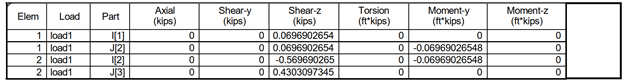
The results are shown below.
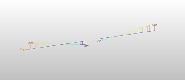
Moment (ft-kips)
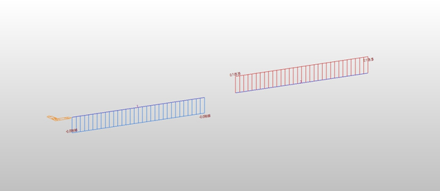
Shear (kips)
Results (ft, kips)
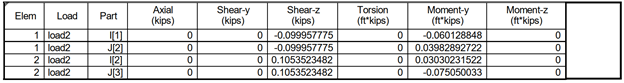
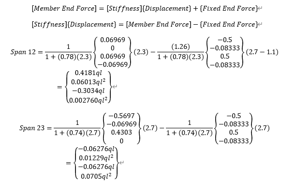
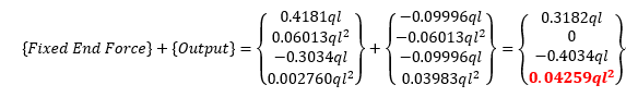
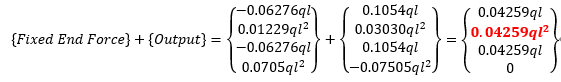
Finally, the member end forces are
Span AB
Span BC


Add a Comment